 |
|||
|
|
|||
|
|
|||
| ||||||||||
|
|
 4-8
TM 9-2815-221
TESTS AND ADJUSTMENTS (CONTINUED)
C Method 1 (PSU only)
D Method 2
and 50)
(1) Record button thickness and
dimensions stamped
NOTE
on mounting flange of defective pump.
Use standard timing button (no. 11).
(2) Record pc dimension of new pump.
see table, p 3-59; model
50, see p 4-12).
(3) Calculate correct button thickness.
EXAMPLE
PC dimension of defective pump
(a)
1.109
Button thickness of defective pump +0.107
Total of A and B
1.216
Subtract pc dimension of new pump
(d)
(e)
Button thickness for new pump
0.113
Select button from list on page 3-66 with
(f)
thickness closest to number in step
(For this
example use button 3, Code C.)
(4) Install correct size button in new fuel injection pump.
(5) Install fuel injection pump (p 3-66).
Install
injection pump (model PSU, p 3-72;
model 50, p 3-88).
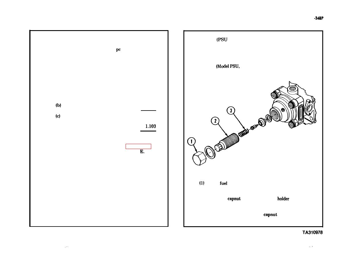
(2) Remove
(l), delivery valve
(2), and
spring (3).
(3) Install valve holder (2) and
(l).
|
|
Privacy Statement - Press Release - Copyright Information. - Contact Us |