 |
|||
|
|
|||
|
|
|||
| ||||||||||
|
|
 TM 9-2520-270-34
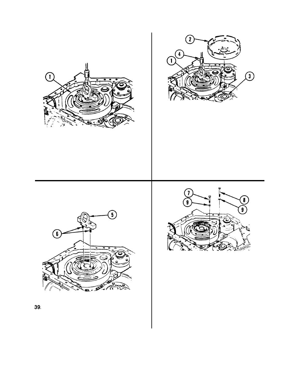
38. INSTALL HYDRAULIC ASSEMBLY (1).
a.
Place clutch housing (2) on gearshaft
spline (3).
b. Turn clutch housing (2) back and forth
until teeth in spur gear mesh with
hydraulic assembly (1). Continue back
and forth turning until hydraulic
assembly is fully seated.
37. ALINE HYDRAULIC ASSEMBLY (1).
c.
Remove clutch housing (2).
a. Aline hydraulic assembly (1) by
moving it back and forth.
d.
Remove lifting device (4).
40. INSTALL SEVEN SHORT BOLTS (7)
AND ONE LONG BOLT (8) WITH
EIGHT WASHERS (9).
a.
Coat threads of short seven bolts (7)
and one long bolt (8) with sealant
compound.
b.
Install eight washers (9), seven
short bolts (7), and one long bolt (8).
REMOVE FIXTURE REMOVAL
ASSEMBLY (5).
41. USING 1/2-lNCH DRIVE TORQUE
WRENCH, TORQUE SEVEN BOLTS (7)
a. Loosen two screws (6) until removal
AND BOLT (8) TO 85-95 ft-lb (12-13 mkg).
assembly (5) can be removed.
GO TO NEXT PAGE
4-385
|
|
Privacy Statement - Press Release - Copyright Information. - Contact Us |