 |
|||
|
|
|||
|
|
|||
| ||||||||||
|
|
 TM 9-2520-270-34
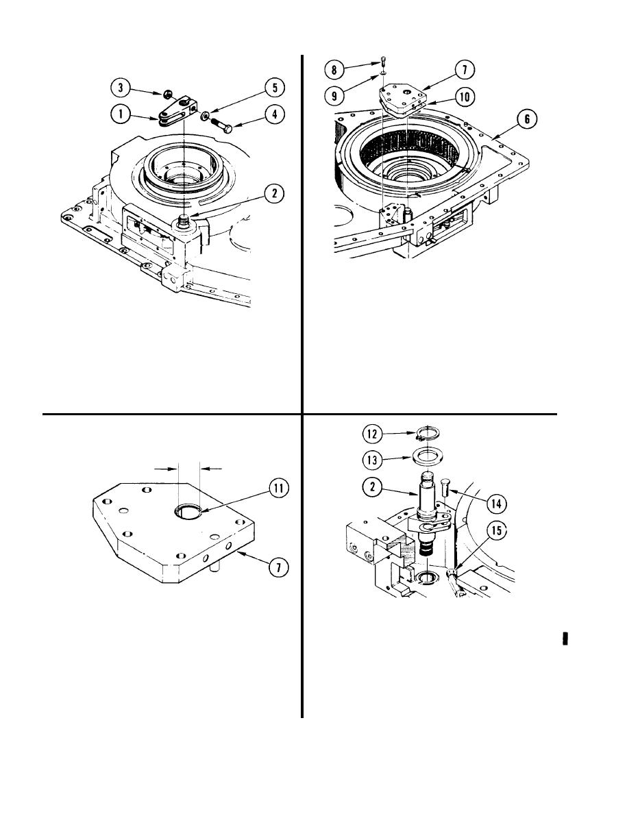
4. REPAIRER AND HELPER TURN
OUTPUT HOUSING (6) OVER.
5. REMOVE VALVE PLATE ASSEMBLY (7).
3.
IF LEVER ARM (1) IS
a.
Using 3/8-inch drive brace handle
INSTALLED, REMOVE FROM
and 7/16-inch socket, remove five
SHOULDERED SHAFT (2).
screws (8) and washers (9).
a. Remove self-locking nut (3),
b.
Using plastic-faced hammer, remove
screw (4) and washer (5).
plate (7) and gasket (10).
b. Remove lever arm (1) from shaft (2).
Discard gasket.
7. REMOVE SHOULDERED SHAFT (2).
a.
Using retaining-ring pliers, remove
6. CHECK VALVE PLATE ASSEMBLY (7),
and discard retaining ring (12).
a.
Using micrometer caliper set and
b. Remove shim (13).
telescoping gage set, measure
Remove pin (14) and slide rod end
c.
inside diameter of bushing (11).
connector (15) out of shaft (2).
Replace plate (7) if measurement is
greater than 0.7513 inch (19.083 mm).
d.
Remove shaft (2).
4-280
Change 1
|
|
Privacy Statement - Press Release - Copyright Information. - Contact Us |