 |
|||
|
|
|||
|
|
|||
| ||||||||||
|
|
 TM 9-2520-270-34
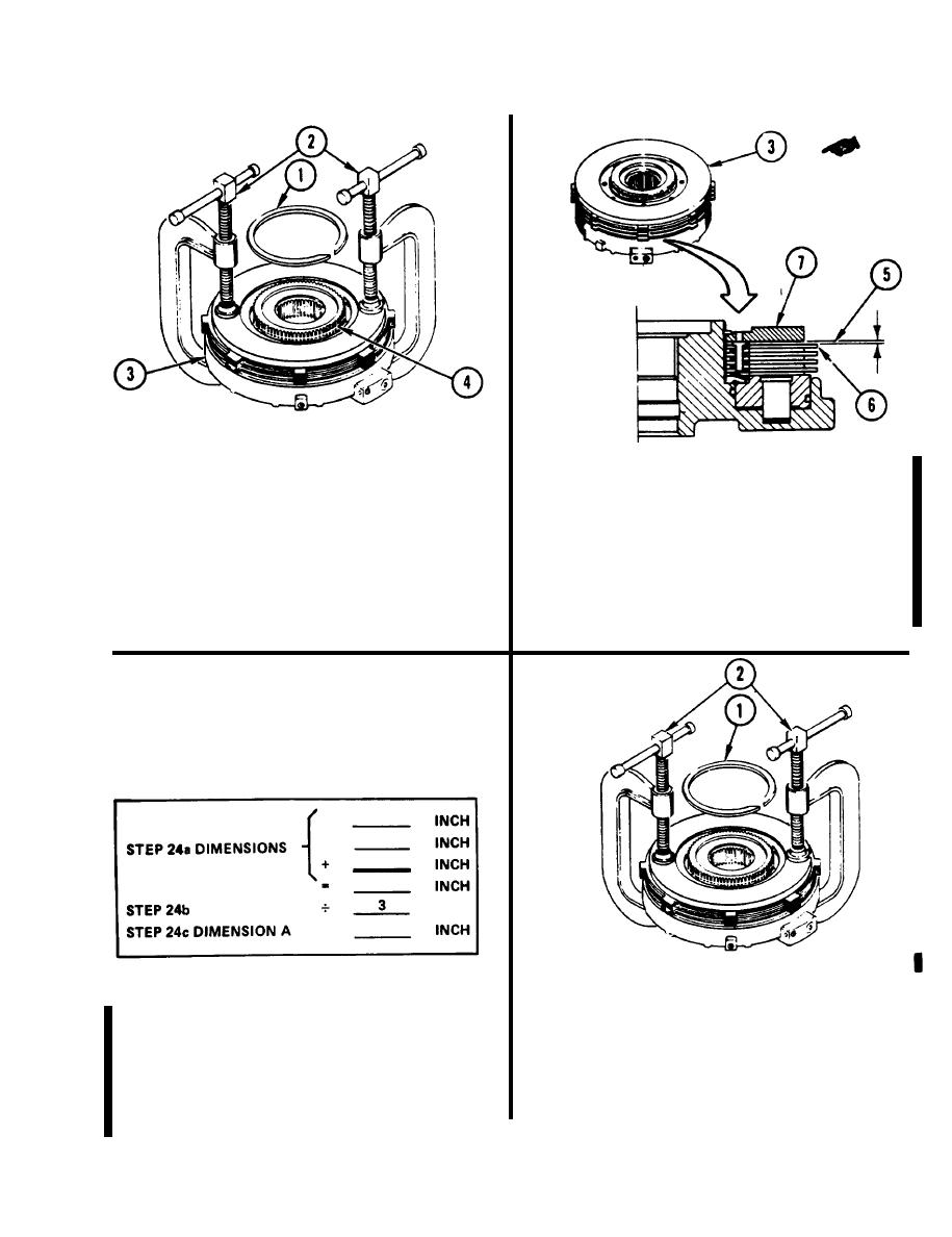
22. INSTALL RETAINING RING (1).
23. CHECK CLEARANCE (5) IN FRICTION
a. Place two "C" clamps (2) on clutch
C L U T C H ASSEMBLY (3).
assembly (3) opposite each other.
a. Measure clearance between clutch
b. Tighten two "C" clamps (2) evenly until
friction plate (6) and backup Plate (7) in
retaining ring groove (4) can be seen.
three places.
c. Using retaining-ring pliers, install
b. If clearance (5) is 0.055 to 0.075 inch
retaining ring (1).
(1.40 to 1.90 mm), go to END OF TASK. If
not, go to step 24.
d. Remove two "C" clamps (2).
24.1 REMOVE RETAINING RING (1).
Place two "C" clamps (2) on clutch
a.
24. OBTAIN DIMENSlON A.
assembly (3) opposite each other.
Add three dimension obtained in
a.
b. Tighten two "C" clamps (2) evenly to
step 23a.
relieve pressure on retaining ring (1).
Divide results of step 24a by three.
b.
Using retaining-ring pliers, remove
c.
retaining ring (1).
Record results as dimension A.
c.
GO TO NEXT PAGE
4-216.1 (4-216.2 blank)
Change 3
|
|
Privacy Statement - Press Release - Copyright Information. - Contact Us |
