 |
|||
|
|
|||
|
|
|||
| ||||||||||
|
|
 TM 9-2520-270-34
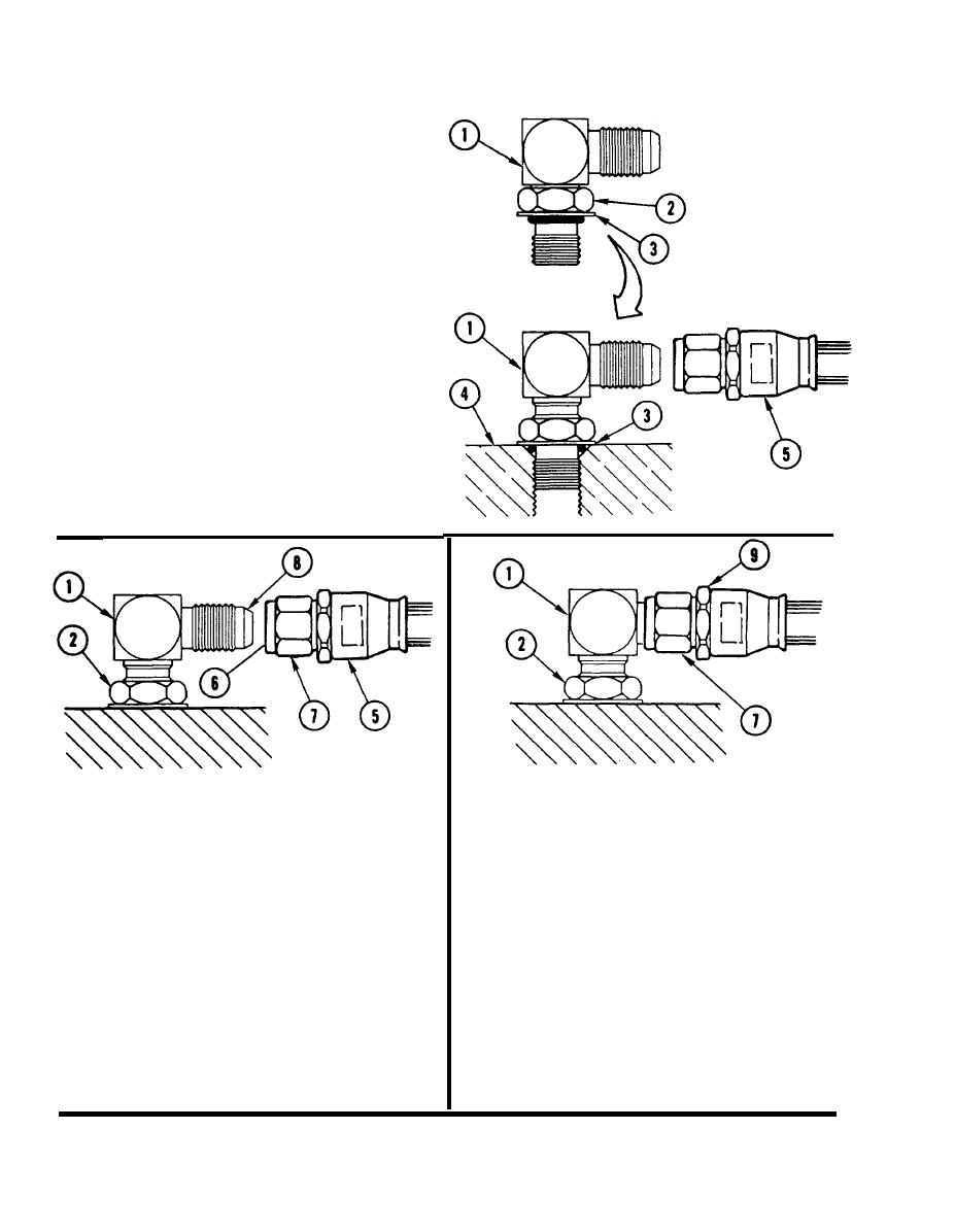
3 . INSTALL ELBOW (1).
a. Turn locknut (2) toward captive
washer (3) until locknut touches captive
washer.
Screw elbow (1) into housing (4) until
b.
captive washer (3) touches housing.
Turn elbow (1) to position needed for
c.
connection to hose assembly (5).
USING OPEN-END WRENCH, HOLD HOSE
6.
NUT (9).
CAUTION
Do not twist hose assembly when connecting
7.
USING 3/8-INCH DRIVE TORQUE
to elbow. Damage to equipment can occur.
WRENCH AND 9/16-lNCH CROWFOOT,
TORQUE SWIVEL NUT (7) TO
4. CONNECT HOSE ASSEMBLY (5).
125-135 IN-LB (144-155 cmkg).
a. Aline cup seat (6) inside swivel nut (7)
with elbow cone (8).
RETORQUE LOCKNUT (2) ON
8.
ELBOW (1).
b. Connect and hand tighten hose
assembly (5) to elbow (1).
Loosen locknut (2) on elbow (1) to zero
a.
torque.
HOLD ELBOW (1). USING 3/8-lNCH DRIVE
5.
Hold elbow (1) from turning.
b.
TORQUE WRENCH AND 9/16-INCH
Torque locknut (2) to 125-135 in-lb
c.
CROWFOOT, TORQUE LOCKNUT (2) TO
(144-155 cmkg).
125-135 IN-LB (144-155 cmkg).
END OF TASK
Change 3
2-180
|
|
Privacy Statement - Press Release - Copyright Information. - Contact Us |