 |
|||
|
|
|||
|
Page Title:
Install six internal-splined disks |
|
||
| ||||||||||
|
|
 TM 9-2520-249-34&P
NOTE
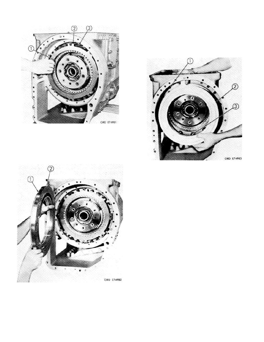
When installing the cam, the flat area (2) on
the largest circumference must be at the
top and inclined slightly toward the rear of
J the bevel gear housing.
18. Install six internal-splined disks (1) and six
external-tanged disks (2) beginning with an
internal splined and alternately installing
external-tanged and internal-splined disks.
Install 12 clutch release springs (3) on the spring
pins.
20. Install sixteen 3/8-16 x 1-1/2 inch, self-locking
bolts (1) and sixteen flat washers. Tighten the J
bolts to 36 to 43 pound feet torque. Install 12
steel balls (3) into the pockets in the stationary
cam, using oil-soluble grease to retain them.
Install left brake rotating cam (2), seating it
against the steel balls.
Rotate the cam
clockwise to maximum release position.
19. Install left brake stationary cam ring (1), with its
seal ring, and seat it against the piston return
springs.
8-12
|
|
Privacy Statement - Press Release - Copyright Information. - Contact Us |