 |
|||
|
|
|||
|
|
|||
| ||||||||||
|
|
 TM 9-2520-249-34& P
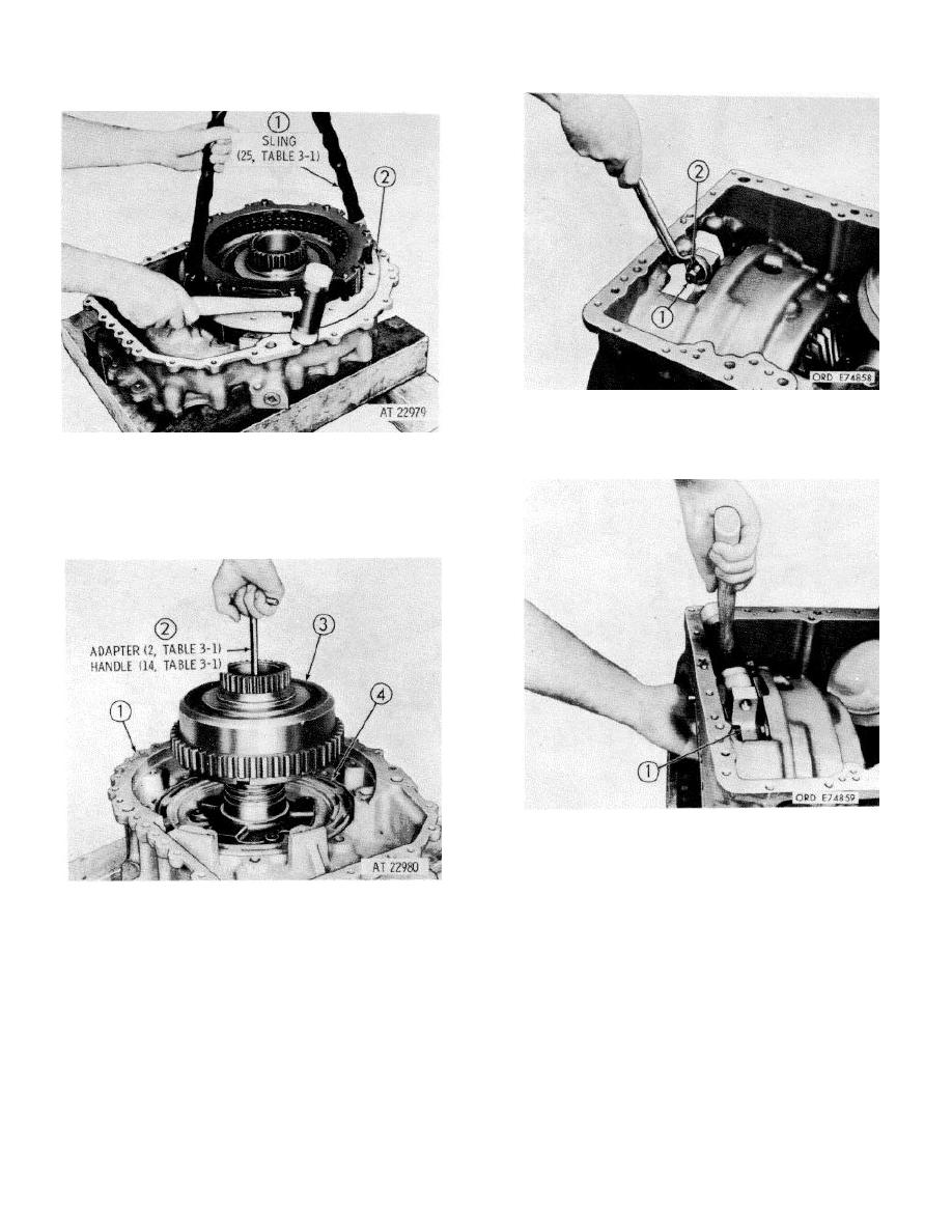
56. Using a 15/16-inch wrench, loosen lock nut (2)
on brake adjusting screw (1). Use a 5/8-inch
wrench, if necessary, and remove the adjusting
screw and locknut.
54 Attach two legs of sling (1) using two of the bolts
removed, to the brake and steer clutch
assembly (2). Remove the assembly by tapping
the housing lightly with a soft hammer while
lifting with the hoist. Remove the sling.
57 Grasp brake apply rotating cam (1) with one
hand. Using a soft hammer, drive the cam lug
toward the front of the bevel gear housing to
loosen the cam. Place a container beneath the
brake cam to catch the 12 steel balls that will
55 Install handle and adapter (2) into output clutch
fall during removal of the cam.
assembly (3). Remove the clutch assembly by
lifting the handle. Remove steer clutch piston
(4) by applying air pressure in passage (1).
Remove the handle and adapter.
6-16
|
|
Privacy Statement - Press Release - Copyright Information. - Contact Us |