 |
|||
|
|
|||
|
|
|||
| ||||||||||
|
|
 TM 9-2520-238-34
REPAIR OUTPUT SHAFT ASSEMBLIES -- Continued
0024 00
3.
Inspect the bore and machine groove in the piston ring retainer for wearing and deformation. Replace defective retainer.
4.
Inspect screw thread inserts in output shaft supports for damaged threads and loose fit. Replace inserts that are loose or
have damaged threads.
ASSEMBLY
NOTE
Steps 1 - 13 apply to right output shaft assembly.
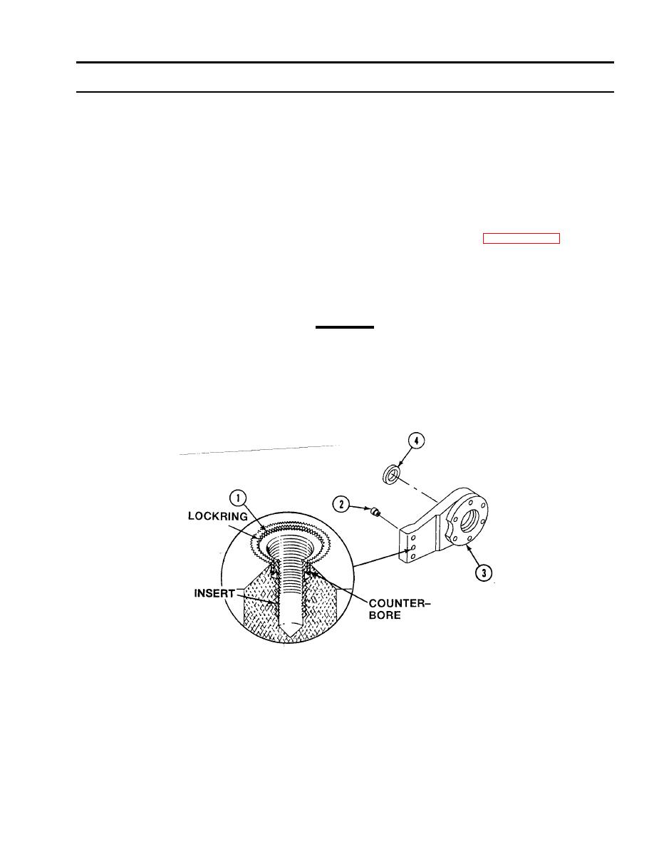
If serrated lockring screw thread insert in output shaft support was removed in page 0024 00-2,
do Steps 1 - 3.
1.
Remove lockring (1) from insert (2).
2.
Install insert (2) into tapped hole of output shaft support (3) by turning insert to the right.
CAUTION
Do not drive lockring below top surface of insert. Insert threads may loosen.
3.
Drive lockring (1) into tapped hole in output shaft support (3) until inserter tool touches surface. Lockring will be set at
proper depth.
4.
Thoroughly clean mating surface of new encased oil seal (4) with cleaning compound.
5.
Apply a thin film of sealing compound to outer edge of oil seal (4).
0024 00-7
|
|
Privacy Statement - Press Release - Copyright Information. - Contact Us |