 |
|||
|
|
|||
|
Page Title:
Remove steering brake adjusting nut |
|
||
| ||||||||||
|
|
 TM 9-2520-238-34
REPAIR BRAKE SHOE ASSEMBLIES -- Continued
0022 00
2.
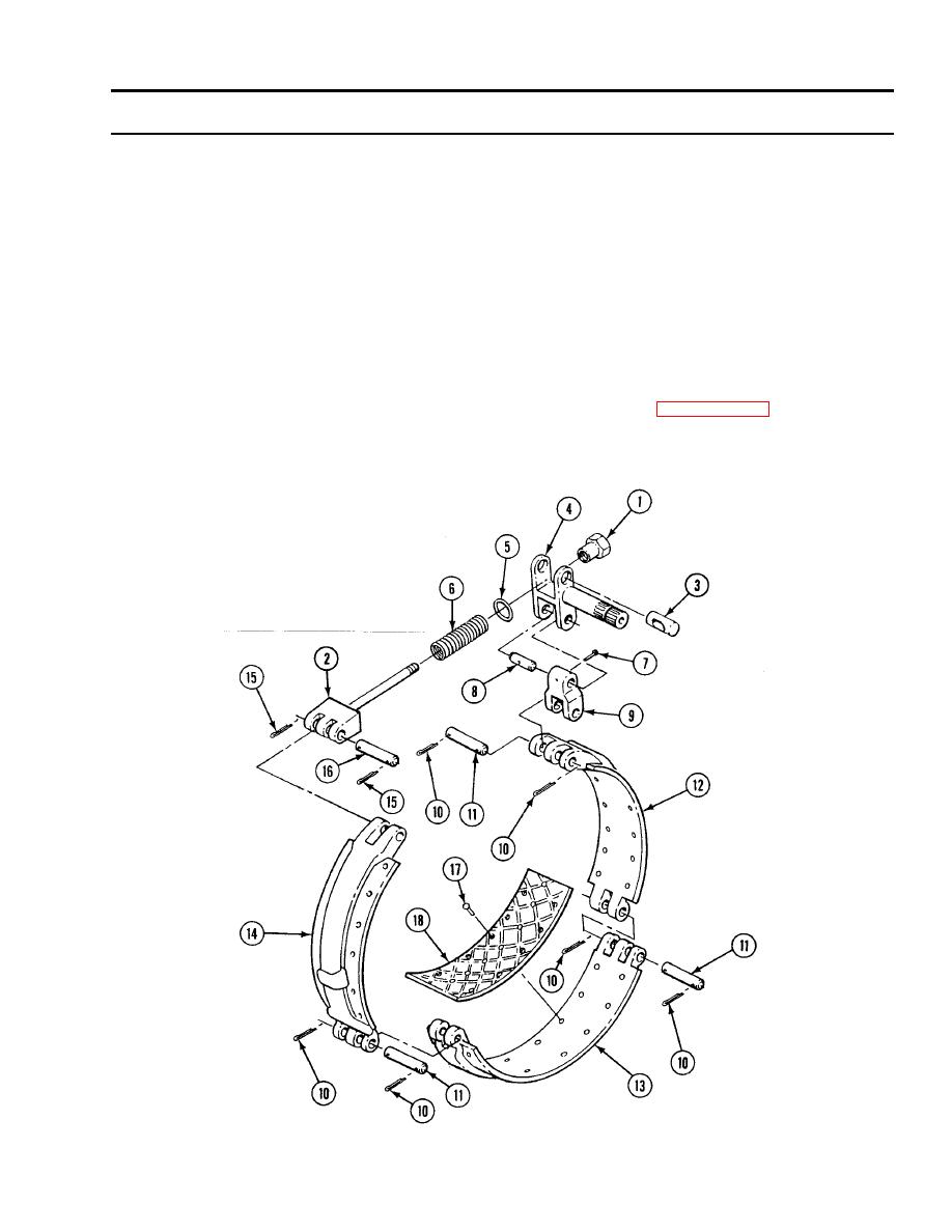
Remove steering brake adjusting nut (1) from rod end clevis (2). Remove clevis and pin (3) from steering brake shaft (4).
Remove washer (5) and helical spring (6) from clevis (2).
3.
Remove solid rivet (7) and pin (8) holding steering brake shaft (4) to link (9). Separate pin and brake shaft from link.
Discard rivet.
4.
Remove six cotter pins (10) and three straight headless pins (11). Separate brake shoe (12), brake shoe (13), and brake
shoe (14). Discard cotter pins and straight pins.
5.
Remove two cotter pins (15) and straight headless pin (16). Separate rod end clevis (2) from shoe (14). Discard cotter
pins and straight pin.
NOTE
If inspection indicates brake friction linings must be replaced, do (page 0022 00-8).
6.
Remove 12 tubular rivets (17) from each friction lining (18) on brake shoe (12), brake shoe (13), and brake shoe (14).
Discard friction linings and rivets. Use drill and twist drill set.
0022 00-3
|
|
Privacy Statement - Press Release - Copyright Information. - Contact Us |