 |
|||
|
|
|||
|
Page Title:
Check and adjust backlash between gears |
|
||
| ||||||||||
|
|
 TM 9-2520-238-34
REPAIR COOLING FAN RIGHT ANGLE DRIVE C (M113A3 FOV ONLY) -- Continued
0016 00
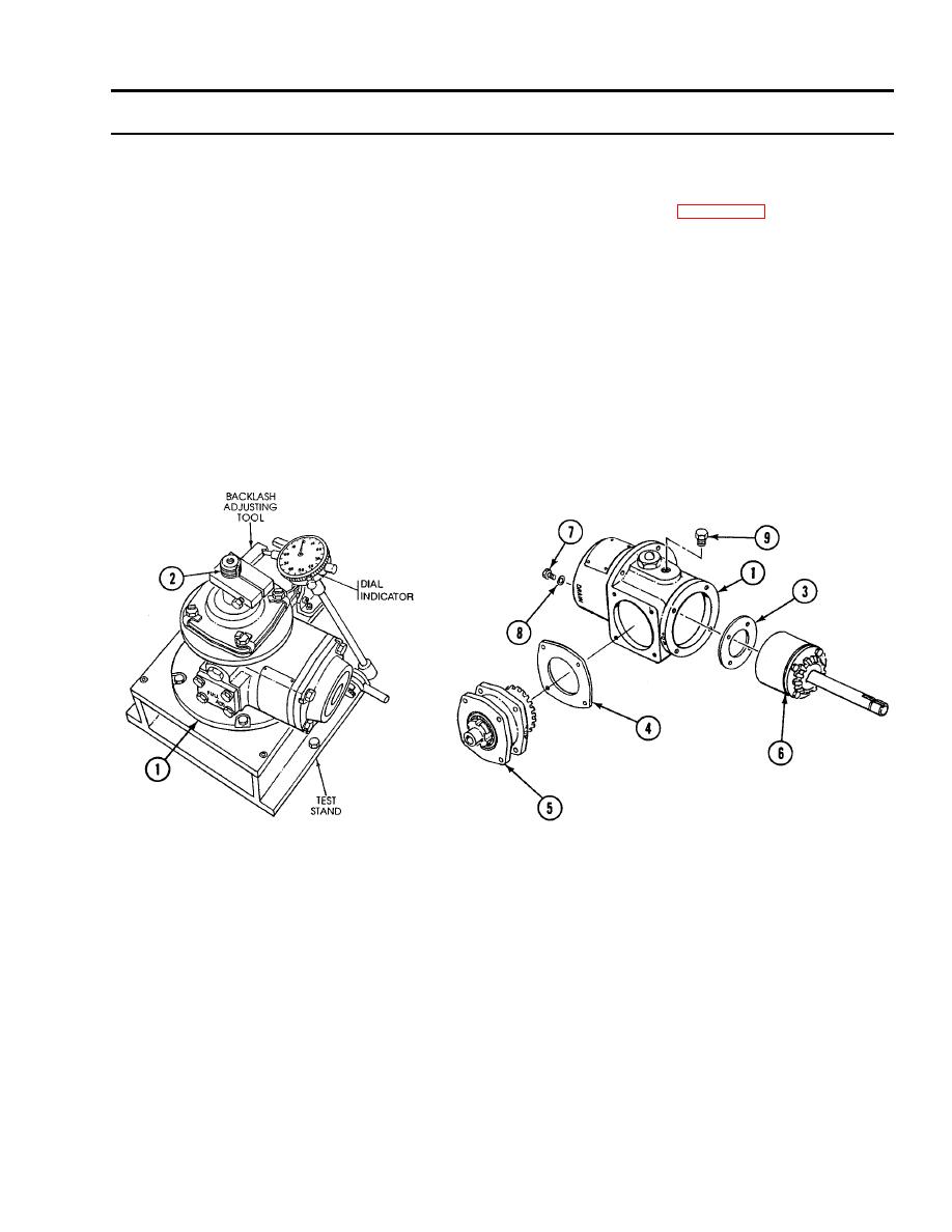
21. Check and adjust backlash between gears as follows:
a.
Install housing (1) in test stand with spindle shaft (2) in up position. Install backlash adjusting tool on spindle shaft
(2) and secure tool by tightening socket head screw on tool. Attach dial indicator (WP 0033 00, Item 13) so that
indicator feeler fits in notch on arm of tool.
b.
Check gear backlash by moving tool from side to side while observing dial indicator. Backlash reading should be
between 0.005 inch and 0.009 inch.
c.
If backlash is less than 0.005 inch, remove more laminates from spindle shim (3) or add laminates to cartridge
shim (4).
d.
If backlash is greater than 0.009 inch, add laminates to spindle shim (3) or remove laminates from cartridge
shim (4).
e.
If required, remove cartridge assembly (5) and spindle assembly (6), install new thickness shim (3) and new
thickness shim (4), and repeat Step 11, Step 16, and Step 19. Then recheck backlash by repeating steps Step 21a
and Step 21b above.
f.
Remove dial indicator and backlash adjusting tool from spindle shaft (2).
0016 00-15
|
|
Privacy Statement - Press Release - Copyright Information. - Contact Us |