 |
|||
|
|
|||
|
Page Title:
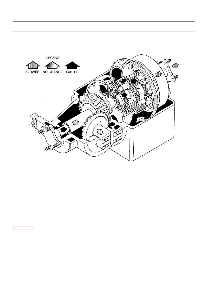
CARRIER MOVING TO RIGHT WITH RIGHT STEERING BRAKE APPLIED |
|
||
| ||||||||||
|
|
 TM 9-2520-238-34
EQUIPMENT DESCRIPTION AND DATA -- Continued
0002 00
CARRIER MOVING TO RIGHT WITH RIGHT STEERING BRAKE APPLIED. When the right brake is applied, the same
action takes place in the steering unit assembly as described in the left steering brake applied, except the sequence of motion
is from right to left.
Steering Control Differential Right Steer Torque Path
SINGLE DISK PIVOT STEER BRAKE AND HYDRAULIC MASTER BRAKE CYLINDER
GENERAL. Two hydraulic master brake cylinders are connected by linkage to pivot steer levers in the driver's compartment.
Each master brake cylinder is connected by hydraulic hose and tubes to a pivot steer brake that controls rotation of the pivot
steer brake disk mounted on the left and right side of the steering control differential. Actuating the pivot steer lever manually
to the applied position on the inside of a turn causes the rotation of the brake disk, differential output shaft, and track to lock
up on that side. This allows the carrier to make quick turns at low speed (15 mph maximum) and provides steering when
operating in water.
PIVOT STEER BRAKE ASSEMBLY AND HYDRAULIC MASTER BRAKE CYLINDER. Single disk pivot steer brake and
hydraulic brake master cylinder are major components of the pivot steer system installed in carriers listed in Table 11,
(WP 0001 00). In a pivot steer system, the pivot steer brake assembly has two housings mounted together on a flange on each
side of the differential. The pivot steer brake disk rotates in a gap between the two housings. The master cylinder contains a
low pressure piston, high pressure piston, and relief valve. As actuated manually by pivot steer lever, the pistons compress the
hydraulic fluid, causing a rise in the fluid line to the pivot steer brake. The relief valve prevents pressure from exceeding a
preset level.
PIVOT BRAKE APPLIED. When hydraulic pressure of 20 to 40 psi is applied to the piston in each housing from its master
brake cylinder, the release units in the housing simultaneously causes the brake linings to press against each side of the brake
disk to stop the disk from turning.
0002 00-10
|
|
Privacy Statement - Press Release - Copyright Information. - Contact Us |