 |
|||
|
|
|||
|
|
|||
| ||||||||||
|
|
 TM 9-2520-238-34
EQUIPMENT DESCRIPTION AND DATA -- Continued
0002 00
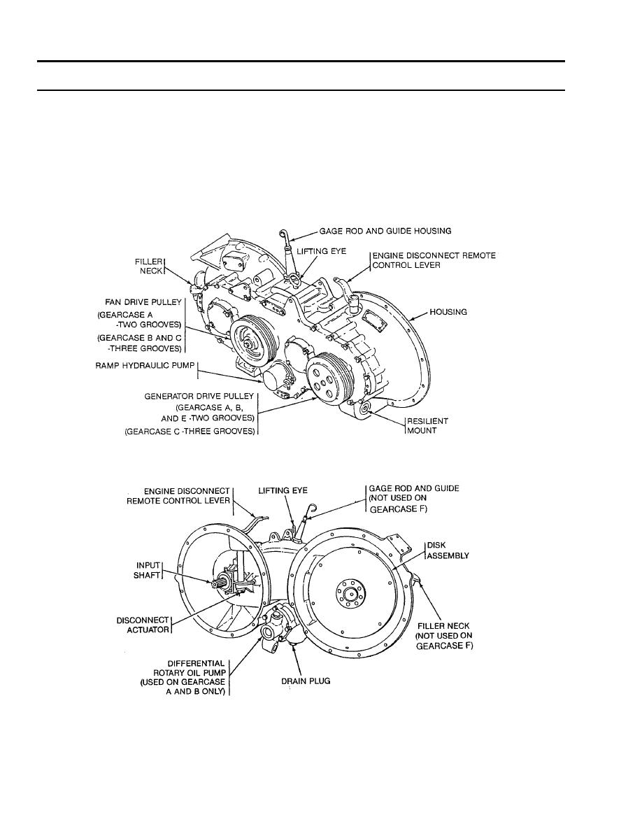
TRANSFER GEARCASE A. Like gearcases B and C, transfer gearcase A is converted from service spare transfer gearcase E.
Gearcase A is used on the M113A1 Family of Vehicles (FOVs). The gearcase has two two-grooved pulleys (one installed on
the input shaft and the other on the hub of the second intermediate gear), a manual engine disconnect remote control lever, an
oil filler assembly, an oil level gauge rod and guide, a differential oil pump, and a ramp hydraulic pump. The two pumps are
driven internally by the secondary pump-drive gear. The gearcase is filled with oil through a filler assembly and is drained
through a hole at the bottom of the housing. The output gear ratio is 1.268:1, and the maximum input speed is 2800 rpm.
When the manually operated engine disconnect remote control lever is actuated, the splined input shaft mounted on the roller
bearings and supported by the input gear, is disengaged from the input gear and the gear train but remains engaged with the
power source (engine) to provide a couple between the engine and drive pulley.
Transfer Gearcases A through C, and E Rear View
Transfer Gearcases A through F Front View
0002 00-4
|
|
Privacy Statement - Press Release - Copyright Information. - Contact Us |