 |
|||
|
|
|||
|
Page Title:
Inspection Cables and Wiring Harness Assemblies |
|
||
| ||||||||||
|
|
 TM 750-245-4
CAUTION
Cut the end of nylon straps off flush
with the boss to avoid cuts to hands
from the sharp edges. The plastic
ties may also be used as cable
clamps. Care should be taken that
no cable clamp be placed over a
cable tie.
must be provided to allow opening of an access door,
the harness should be served at the start and end of the
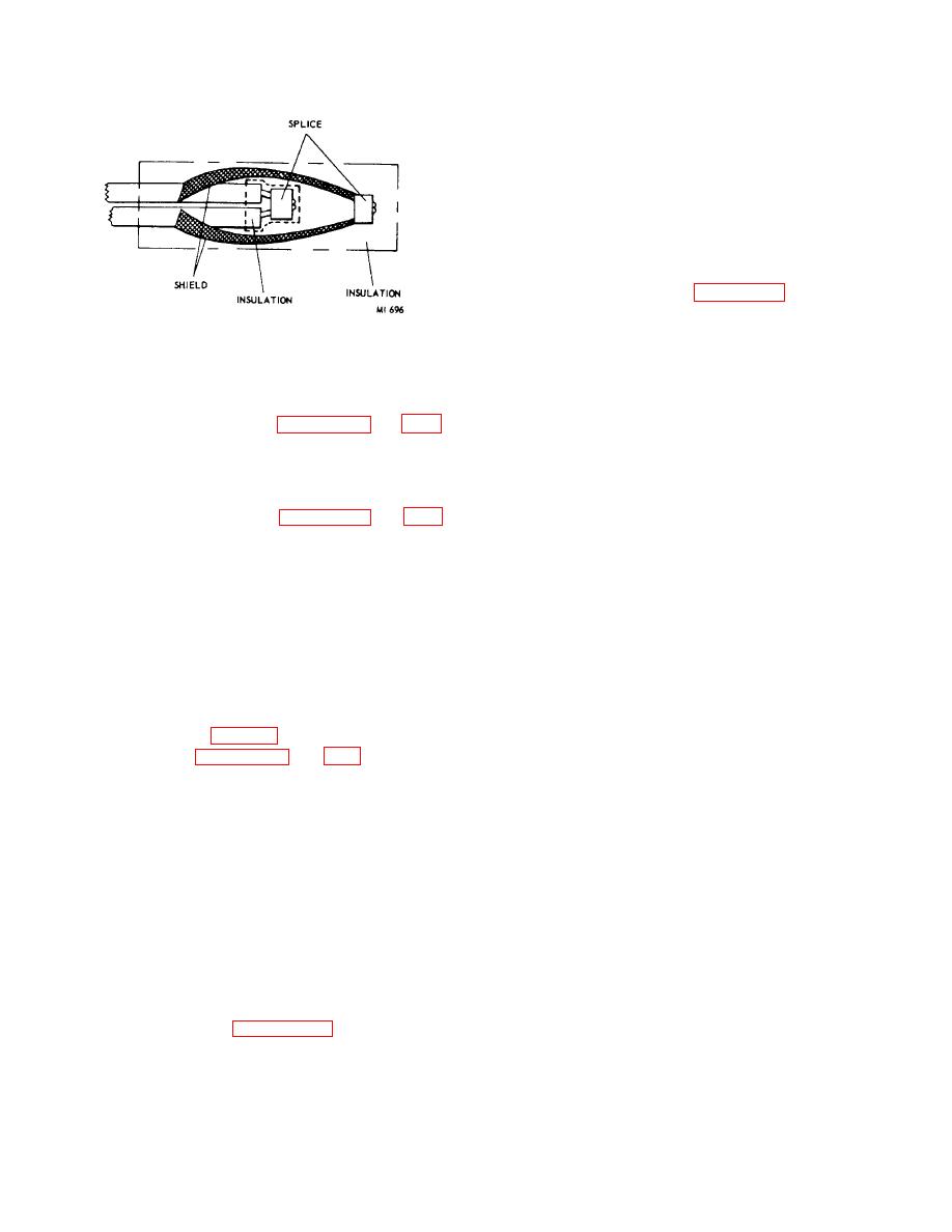
Figure 3-8. Pigtail splice with shield carried
loop. The loop should not be laced, but should be
through.
secured by spot ties or plastic cable ties.
the lacing material around the bundle, over the standing
part, and through the loop.
3-13.
Inspection Cables and Wiring Harness
Assemblies
(4) Single lock stitch (figures 3-21 and 3-22).
The single lock stitch is commonly used for continuous
a. After repair of cable and wiring harness, test for
lacing. It is made by making a single stitch, then
electrical continuity and insulation resistance.
passing the free end under the lacing between the two
b. Visual inspection may be made according to the
stitches and through the loop.
following checklist:
(5) Double lock stitch (figures 3-23 and 3-24).
(1) There shall be no fungus growth, oil,
The double lock stitch is used primarily to prevent lacing
grease, corrosion, or foreign materials (especially
from loosening but is frequently used for complete
around pins and terminals).
lacing. It is made by making two single stitches around
(2) Insulation shall have no cracks, tears,
the bundle and securing with a lock stitch.
cuts, fraying, abrasion, burns, or other deterioration
(6) Spacing of stitches.
The wires in a
throughout entire length with particular emphasis at
finished cable trunk should have a minimum number of
splices and terminations.
crossovers. Crossovers, if necessary, should be at least
(3) Connectors, when required, shall have
8 inches from the termination. Terminating stitches
proper application of potting.
should be made at the end of each lacing. The type of
(4) Terminals and connectors shall not be
stitch is determined mainly by the type of insulation and
twisted, bent, broken, or missing.
diameter of the bundle. The most commonly used stitch
(5) Insulator inserts shall not be burned,
spacing is indicated in table 3-1.
cracked, chipped, broken, or contaminated with any
(7) Serve (figures 3-25 and 3-26). The length
foreign material.
of the serve or endless tie should be equal to
(6) Mounting and connector hardware, dust
approximately the outside diameter of the wire bundle
covers, and caps, shall not be loose, damaged, or
and should not exceed 3/4 inch. To prevent the lacing
missing.
from loosening, it should be served at the point of origin
(7) Identification markings shall not be
and at the point of termination of the lacing. The serve
illegible, incorrect, or missing.
is used at bundle branches or breakouts and at all
bundle end terminations. The serve is made by forming
(8) Color or number code of wire shall be in
a loop along the bundle with the lacing tape, the ends of
accordance with system documentation or have a
the tape toward the bundle end. Wrap the lacing end of
suitable marker indicating correct code on each end.
the tape around the bundle and over the loop. Upon
(9) Pin and socket terminal contacts shall be
reaching the desired length of serve, pass the lacing end
securely seated in connector inserts.
through the loop and pull the ends away from each
(10) Insulator blocks must not be free to be
other. Adjust by pulling until the cross is under the
pulled or pushed out.
serve. Cut this excess tape from each end of the serve.
(11) Minimum radii of bend for power wires
(8) Spot ties (figure 3-27). Spot ties are
and cables shall be 10 x od.
frequently used in place of continuous lacing. They are
(12) Minimum radii of bend for power wires
made exactly like the termination ties.
and cables at terminals or support shall be 3 x od.
(13) Minimum radii of bend for RF cables
enclosed in sleeving shall be 2 x od.
3-5
|
|
Privacy Statement - Press Release - Copyright Information. - Contact Us |