 |
|||
|
|
|||
|
Page Title:
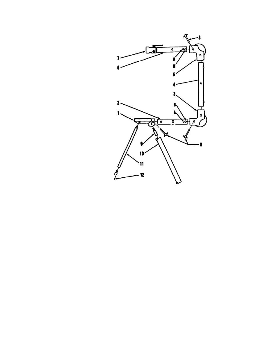
Figure 3-3. Assembly of 7A050 Kit Work Stand and Hoist Structure. |
|
||
| ||||||||||
|
|
 TM 55-4920-201-14
1.
Stand table
8.
Engaging pin
2.
Horizontal tube, no. 2
9.
Stub leg
3.
Elbow
10.
Storage case bottom half
4.
Vertical tube, no. 4
11.
Stand leg
5.
Elbow
12.
Leg extension
6.
Horizontal tube, no. 6
A.
Inner pin hole
7.
Hydraulic pump assembly
B.
Outer pin hole
Figure 3-3. Assembly of 7A050 Kit Work Stand and Hoist Structure.
3-5
|
|
Privacy Statement - Press Release - Copyright Information. - Contact Us |