 |
|||
|
|
|||
|
Page Title:
Table 5-1. Bill of Materials for Blocking and Tiedown of LACV-30 Components on Semitrailers |
|
||
| ||||||||||
|
|
 TM 55-1930-218-14
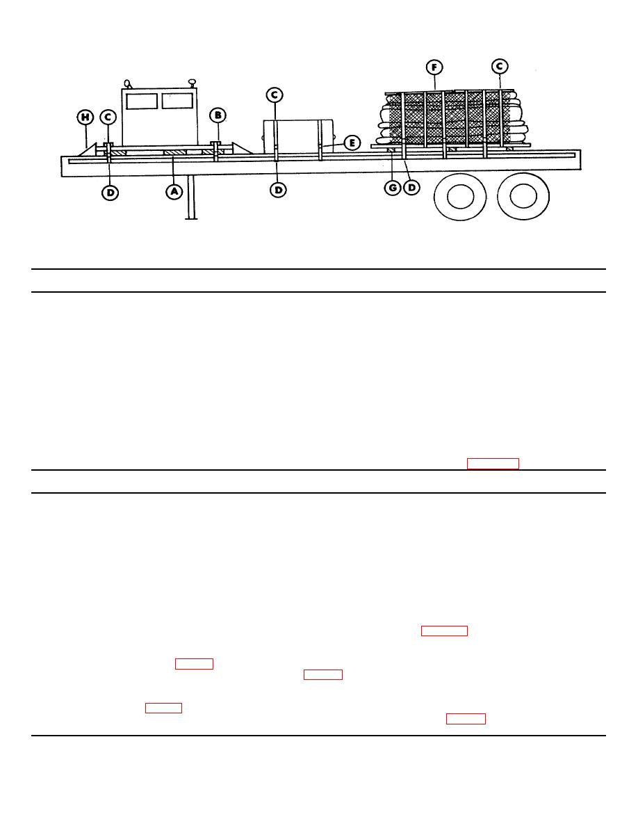
Figure 5-7. Blocking and tiedown of LACV-30 control cabin, bow fenders, and load spreader pallets with peripheral trunk
and cargo net on flatbed trailer.
Table 5-1. Bill of Materials for Blocking and Tiedown of LACV-30 Components on Semitrailers
Approx.
Item
Description
Quantity
Lumber
Douglas fir, or comparable, straight-grain, free from material defects; Fed Spec MM-L-751H:
1-x 4-inch
358 linear ft
4- x 4-inch
40 linear ft
6- x 8-inch
3 linear ft
Plywood
1/2-inch x 4- x 8-foot sheets
4
Styrofoam
Beadboard, 4-inch x 4 x 8-foot (may also be supplied in 4-inch x 2- x 8-foot sheets)
55 sheets
Nylon straps
CGU-1/B tiedown device, 20-foot-long, 5,000-lb-capacity, or equal
5
Strapping
Steel, high tension; Fed Spec QQ-S-781H, type I or IV, 1 1/4- x .035-inch
1,170 ft
Seals
Steel strapping; Fed Spec QQ-S-781H, type D
228
Wire rope
6x19 IWRC; improved plow steel; preformed, regular-lay; table X, Fed Spec RR-W-41OC: 3/8-inch
72 ft
Clamps
Wire rope, U-bolt clips, saddled, single-grip, steel, Crosby heavy-duty, or equal; Fed Spec FF- C-
60
450D: 3/8-inch
Thimbles
Standard, open-type: 3/8-inch
12
Turnbuckles
Eye-and-eye, galvanized, weldless, drop-forged, 5/8-inch eyes, 12-inch take-up
12
Common, steel; flathead; bright; table XI-b, Fed Spec FF-N-105B: 40d
20
Table 5-2. Application of Materials for Tiedown of LACY-30 Components in Figure 5-1
Item
No.
Application
Required
A
Styrofoam Beadboard, 4-inch x 4- x 8-foot sheets, or 4-inch x 2- x 8-foot sheets. Distribute beneath the
sectionalized components to protect the hinge attachment points and to provide separation of the components
from the trailer deck. Position between stacked components to protect the hinge attachment points and to
provide separation between components. Arrange so that approximately 50 to 60 percent of all bottom
surfaces rest on the Styrofoam Beadboard. Position between vehicle ramps and the air management system
(AMS) module before instating item B.
B
5
Nylon straps, 2-inch x 20foot. Using three straps, form a complete loop around both vehicle ramps and
tighten securely. The remaining two straps are joined. Attach one end to the air management system (AMS)
frame underneath one vehicle ramp, pull through the AMS framework across both vehicle ramps, and attach
to AMS frame underneath the vehicle ramp on opposite side.
C
21
Strapping boards, 1- x 4-inch x cut-to-length. Position under steel straps (item D) across tops of modules and
on sides of modules where straps would otherwise contact modules.
D
7
Steel straps, 11/4- x .035-inch x cut-to-length. Position as shown in figure 5-1. Each strap is fabricated by
looping a length of strapping through the stake pocket on each side of the trailer, with a pad (item E) between
the strap and the trailer stake pocket. The loops are formed by attaching a seal (item F) at the overlap areas
(detail 3, fig 7-10). Overlap the two lengths of strapping at the top of the load, tighten, and seal. All seals
must have two pairs of crimps (detail 4, fig 7-10). Secure steel strapping to strapping boards (item C) with
staples or nails.
E
14
Pad, 1 14- x .035 x 18-inch steel strap. Position under and seal to item D at each trailer stake pocket (detail
3, fig 7-10).
F
35
Seal, steel strapping. Required for joining strapping at each joint (detail 4, fig 7-10) and for securing each pad
C(item E) to strap.
5-5
|
|
Privacy Statement - Press Release - Copyright Information. - Contact Us |