 |
|||
|
|
|||
|
Page Title:
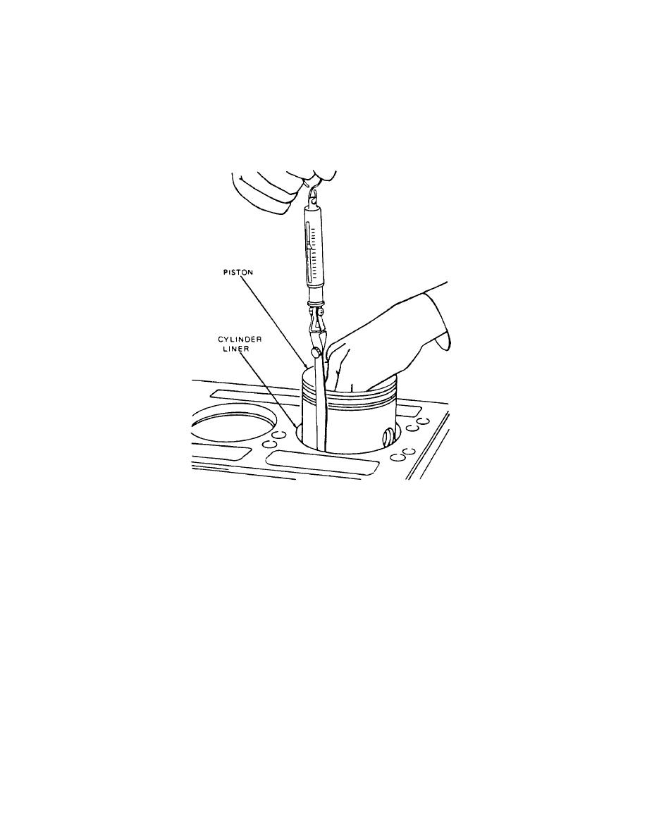
Figure 4-31. Measuring Piston-to-Liner Clearance Using Tool J5438-01 |
|
||
| ||||||||||
|
|
 TM 55-1930-208-24
(14) Select a feeler gage with a thickness that will require a pull of six pounds to remove. The clearance will be .001
inch greater than the thickness of the feeler gage used, i.e., a .004 inch feeler gage will indicate a clearance of
.005 inch when it is withdrawn with a pull of six pounds. The feeler gage must be perfectly flat and free of nicks
and bends.
(15) If any bind occurs between piston and liner, examine the piston and liner for burrs. Remove burrs with a fine hone
(a flat one is preferable) and recheck clearance.
Figure 4-31 .
Measuring Piston-to-Liner Clearance Using Tool J5438-01 .
NOTE
All new piston rings must be installed whenever a piston is removed, regardless of whether a new or used
piston or cylinder liner is attached.
4-39
|
|
Privacy Statement - Press Release - Copyright Information. - Contact Us |