 |
|||
|
|
|||
|
Page Title:
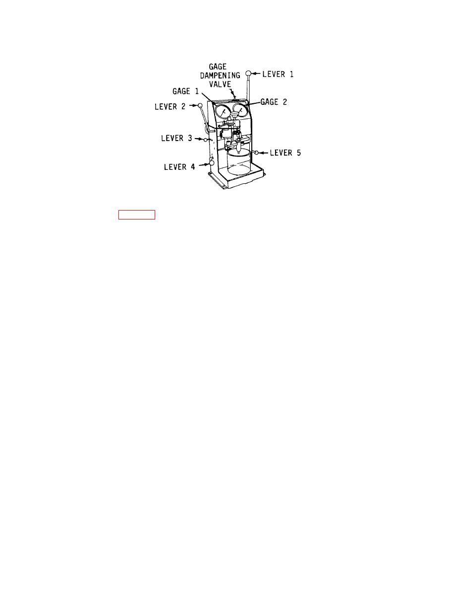
Figure 3-54. Injector in Position for Testing. |
|
||
| ||||||||||
|
|
 TM 55-1930-208-24
Figure 3-54. Injector in Position for Testing.
(13) Refer to figure 3-53. Back off the Thru-Flow Valve halfway.
(14) Hold the clamping head in position over the filter caps and, with the left hand, operate pump
lever 1 evenly to move the clamping head down to seal the filter caps. Be sure the Thru-Flow
Valve moves freely.
(15) Move lever 4 down and operate pump lever 1 to produce a test oil flow through the injector.
(16) Continue pumping lever 1 until air bubbles no longer pass through the discharge tubing.
(17) Be sure lever 4 is down an set the injector rack in the full-fuel position.
(18) Place pump lever 1 in vertical position.
(19) Move lever 3 to forward detent position.
(20) Pump injector lever 40 to 80 strokes per minute. Observe the spray pattern and check that all
spray orifices are open and dispersing the test oil evenly. The beginning and ending of injection
should be sharp and the test oil should be finely atomized.
(21) Note the highest reference gage pressure or Gage No. 2. It should be between 127 and 146.
(22) Stop pumping and close the Thru-Flow Valve. Be sure lever 4 is down.
(23) Operate pump lever 1 to build pressure up to 1600 to 2000 psi (11,024 to 13,078 kPa) on Gage
No. 1.
(24) Check for leakage at the filter cap gaskets, body plugs, and nut seal ring. Open the Thru-Flow
Valve and allow the pressure to bleed off.
3-85
|
|
Privacy Statement - Press Release - Copyright Information. - Contact Us |
