 |
|||
|
|
|||
|
Page Title:
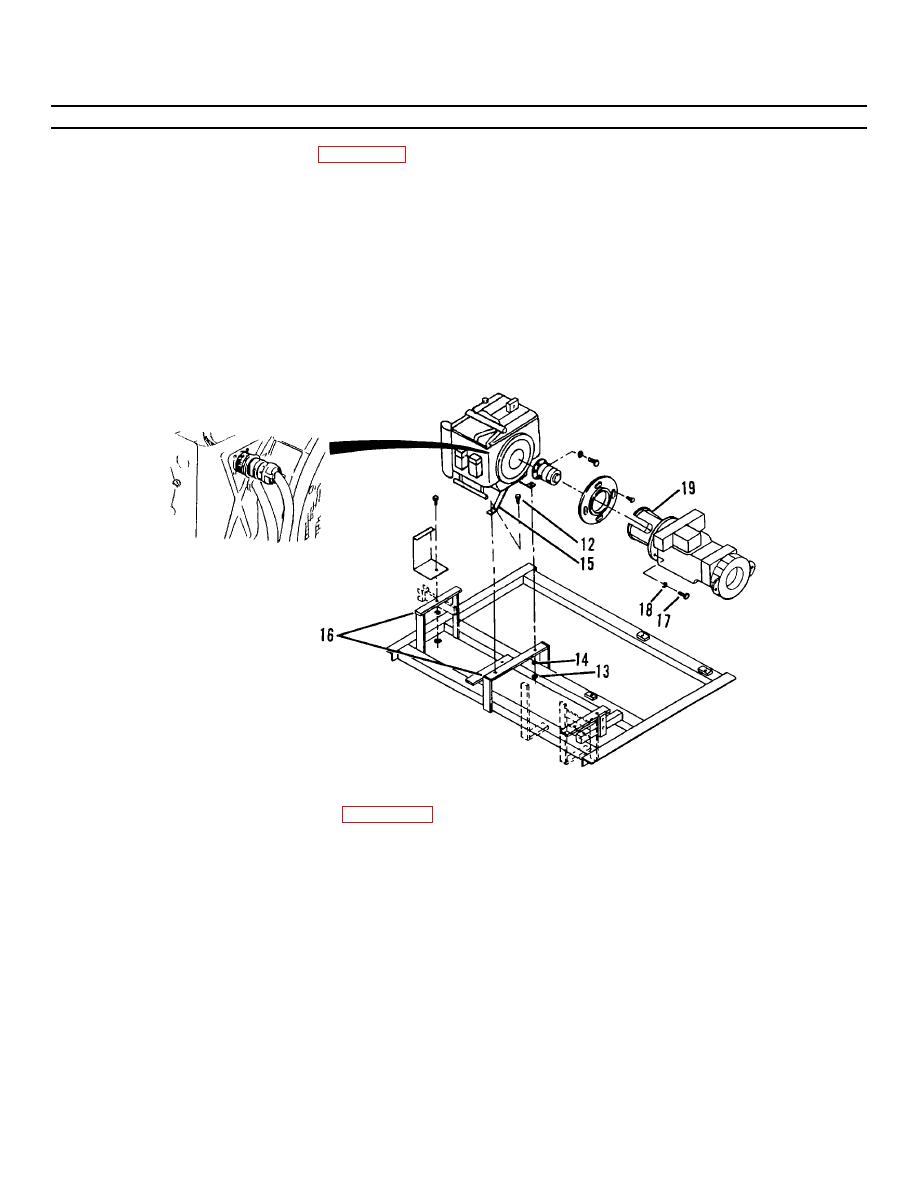
Figure 4-45.1. Engine Mounting. |
|
||
| ||||||||||
|
|
 TM55-1730-228-13&P
4-33. ENGINE - REPLACE (Continued)
4-33
(11) Remove two capscrews (1, Figure 4-45) and washers (2) securing hydraulic pump manifold block assembly
(3) to transmission (4).
(12) Carefully lay manifold block assembly (3) to one side.
(13) Remove nuts (5) on U-bolt (6). Remove U-bolt (6).
(14) Tag seven hydraulic hoses to transmission for ease of identification during installation.
(15) Remove seven hydraulic hoses from transmission. Plug hoses and ports to preven foreign matter from
t
entering system.
(16) Tag the two transmission control solenoid connections (7 and 8) and remove screws securing the
connectors.
Figure 4-45.1. Engine Mounting.
(17) Remove three capscrews (12, Figure 4-45.1), nuts (13) and washers (14) securing engine mounts (15) to
engine rack mounting brackets (16).
(18) Lift engine and transmission vertically and remove to suitable work area.
NOTE
Install suitable sling and hoist around transmission for support.
(19) Remove four capscrews (17) and lockwashers (18) securing transmission mount (19).
(20) Set transmission on clean surface. Care must be taken so that spider coupling between transmission and
engine draft coupling is not lost.
GO ON TO NEXT PAGE
4-117
|
|
Privacy Statement - Press Release - Copyright Information. - Contact Us |