 |
|||
|
|
|||
|
Page Title:
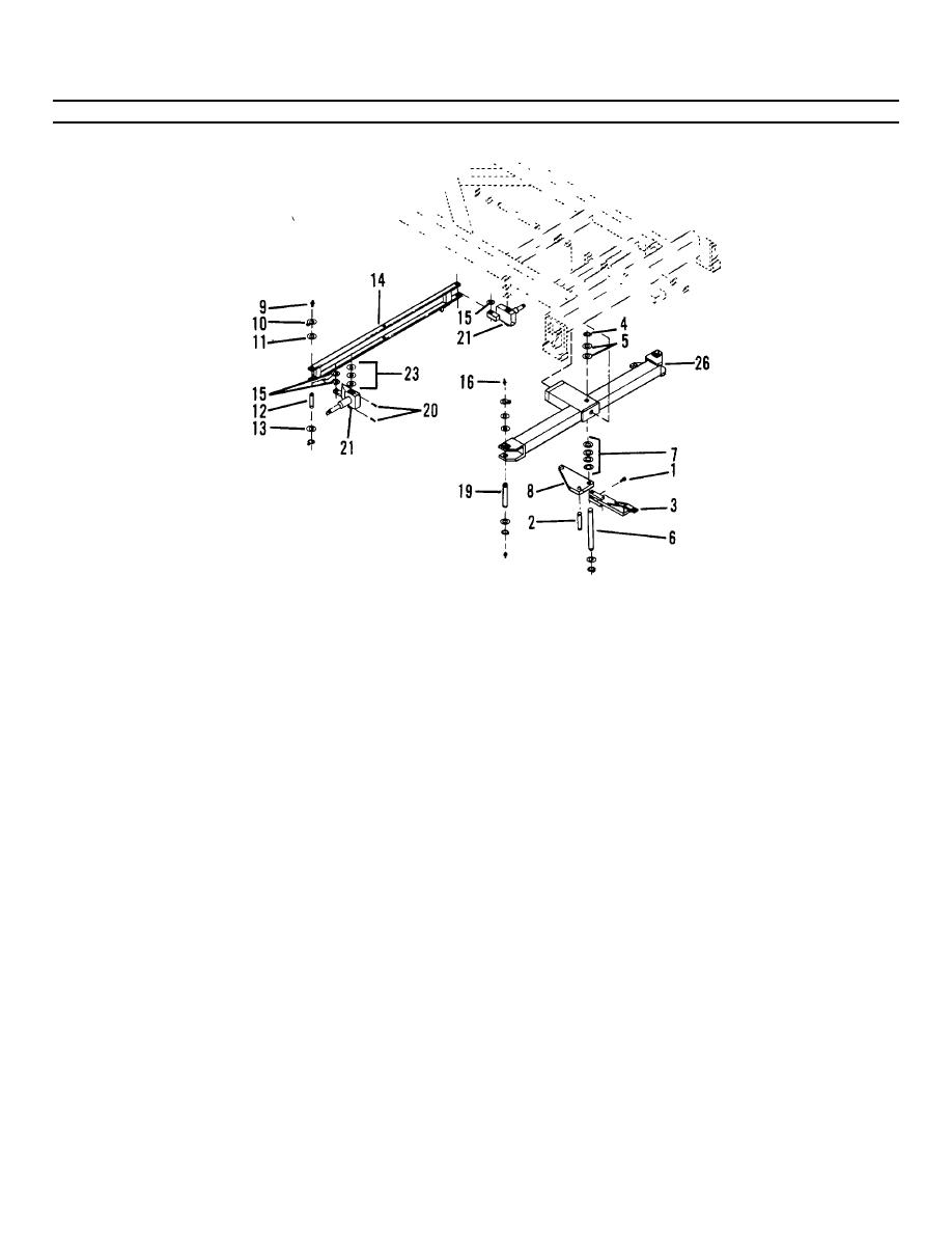
Figure 4-26. Steering Assembly (Sheet 3 of 3). |
|
||
| ||||||||||
|
|
 TM 55-1730-228-13&P
4-23. STEERING ASSEMBLY - REPLACE (Continued)
4-23
Figure 4-26. Steering Assembly (Sheet 3 of 3).
(5) Position spindles (21) and spacers (23) in axle assembly (26). Usethe tags for spacer identification.
(6) Install pins (19) and spacers (22) with a soft drift.
(7)
Install spacers (18) and retaining rings (17) on pins (19).
(8) Tighten set screws (20).
(9) Install grease fittings (16) in pins (19).
(10) Position tie bar (14) and spacers (15) on spindles (21). Use the tags for spacer identification.
(11) Install pins (12) and spacers (13) with a soft drift.
(12) Install spacers (11) and retaining rings (10) on pins (12).
(13) Install grease fittings (9) in pins (12).
(14) Install left side by repeating steps (5) thru (13).
(15)
Slide tie rod link (8) in position within the axle assembly (26).
GO ON TO NEXT PAGE
4-80
|
|
Privacy Statement - Press Release - Copyright Information. - Contact Us |
