 |
|||
|
|
|||
|
Page Title:
REMOVING/INSTALLING SPC CIRCUIT CARD ASSEMBLIES (Continued) |
|
||
| ||||||||||
|
|
 TM 9-6920-737-10
REMOVING/INSTALLING SPC CIRCUIT CARD ASSEMBLIES (Continued)
1.
Observe the Diagnostic Test board replacement message example (1). The "Al" identifies one of the four Logic
Card File Assemblies located behind the SPC cabinet doors (2).
2.
Open the designated cabinet door by pressing the three thumb latches at the right hand of each door.
3.
Observe five rows of CCA's (3) installed in the Logic Card File Assembly. The first digit of each 3-digit identifier
104, 206, 309, 416, 522 of the board replacement message example (1) identifies the row where the designated boards
are located.
4.
Observe that the CCA's in each row (4) are inserted in slots numbered from 04 to 32. The la t two digits of the
s
board replacement message example (1): 104, 206, 309, 416, 522 identify the slots where the designated CCA's
are
located. The location of CCA's identified in the board replacement message example (1) are shaded in diagram
(4)
to show their locations.
WARNING
Remove personal rings, bracelets, wristwatches or other metal jewelry before replacing Circuit Card Assemblies. SPC
power remains on to maintain stable operation. Jewelry could short across an electrical circuit and severely burn or shock
you.
CAUTION
CCA's containing Electrostatic Sensitive Devices (ESD's) are identified by yellow pull tabs and must be protected from
static discharges. Keep yellow-tabbed CCA's in special plastic packages and make sure shorting bars are connected
whenever CCA's are not installed in Logic Card File Assemblies.
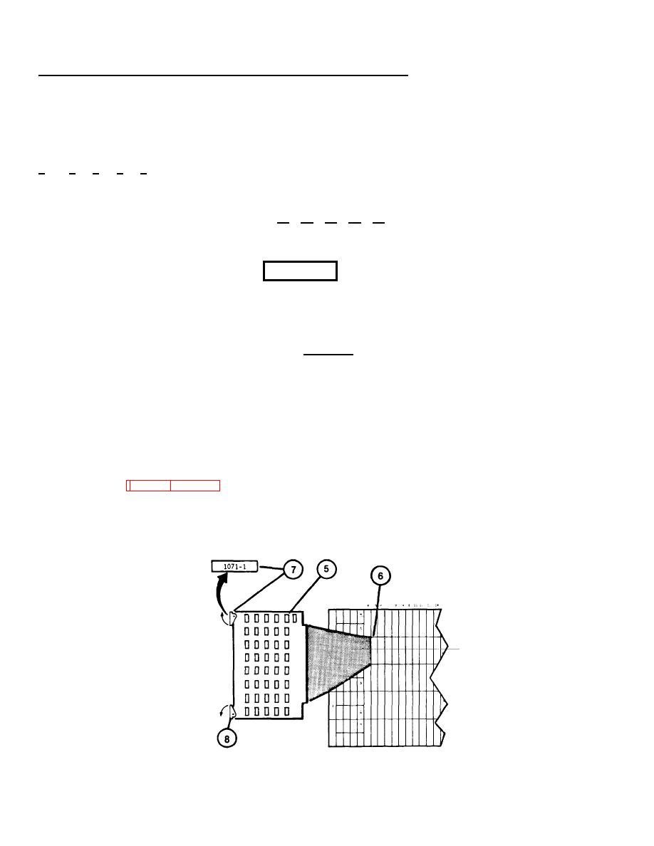
5.
Remove CCA (5) from Logic Card File Assembly (6) as follows:
a.
Record location identification of CCA to be removed (as identified on Display Terminal Diagnostic Test error
message).
b.
Record number of upper pull tab (7) of CCA to be removed. Check recorded number against Table of CCA
Spares (see 3-27 thru 3-30). If CCA is not spared, return to 3-33, step 7T, and identify the next CCA in the
board replacement message.
c.
Slowly, pull tabs (7) and (8) out toward you to loosen the CCA from its socket.
3-25
|
|
Privacy Statement - Press Release - Copyright Information. - Contact Us |
