 |
|||
|
|
|||
|
Page Title:
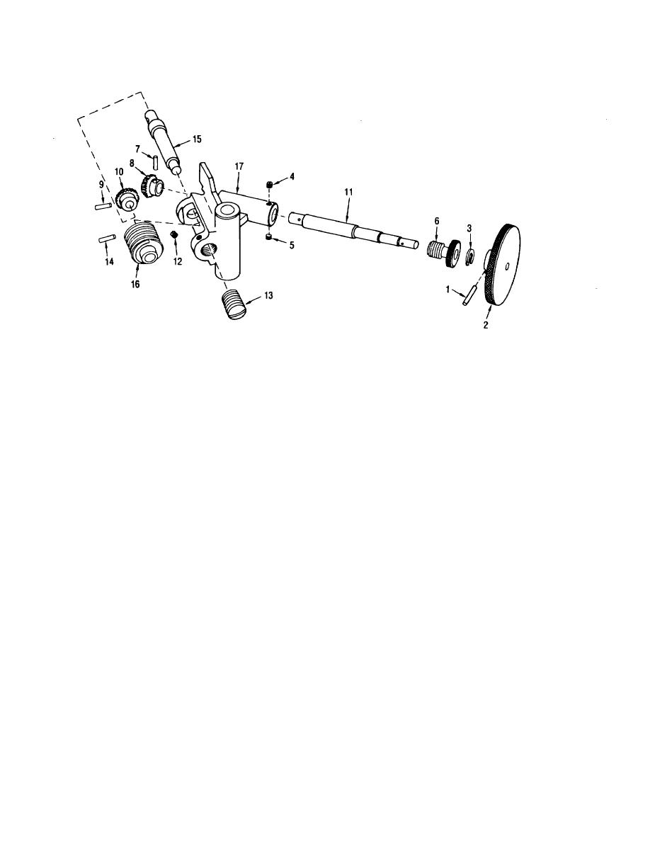
Figure 6-6. Disassembly/assembly of elevating worm gear assembly |
|
||
| ||||||||||
|
|
 TM 9-6920-361-13&P
PRESS GEARS AND HANDWHEEL TIGHT AGAINST SHOULDER AND DRILL 0.078 + 0.004 HOLE TO ACCEPT
SPRING PINS (1, 7, 9, AND 14)
ADJUST SCREW (13) FOR 0.002 MAXIMUM WORM GEAR END PLAY BEFORE TIGHTENING SETSCREW (12).
ADJUST BUSHING (6) FOR 0.002 MAXIMUM HANDWHEEL BACKLASH BEFORE TIGHTENING SETSCREW.
AR 902763
Legend
1. Spring Pin - 11578680
10.
Bevel Gear - 11578650
2. Handwheel - 11578651
11.
Shaft - 11578652
3, Snap Ring - 11578673
12.
Setscrew - 11578672
4. Setscrew - 11578672
13.
Adjusting Screw - 11578657
5. Setscrew - 11578672
14.
Spring Pin - 11578680
6. Bushing - 11578658
15.
Shaft - 11578653
7. Spring Pin - 11578680
16.
Worm Gear - 11578656
8. Bevel Gear - 11578650
17.
Elevating Worm Gear Bracket - 11578709
9. Spring Pin - 11578680
Figure 6-6. Disassembly/assembly of elevating worm gear assembly
6-7
|
|
Privacy Statement - Press Release - Copyright Information. - Contact Us |
