 |
|||
|
|
|||
|
Page Title:
Installation Instructions for the M114A1 Howitzer (cont) |
|
||
| ||||||||||
|
|
 TM 9-6920-361-13&P
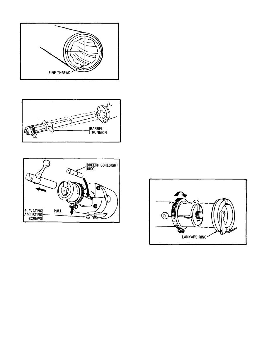
Step 12:
Close the breech, remove the bolt by pulling
down on the locking cap and pulling bolt to the rear. To
boresight the 14.5-mm device:
1. Tighten both elevating adjusting screws
against the barrel.
2. Place the breech boresight disc in the
cartridge chamber.
3. Sighting through the breech boresight disc,
aline the horizontal boresight string of the 14.5-mm
barrel with the horizontal boresight string of the primary
Step 9: Attach fine thread across the four witness marks
weapon by adjusting the elevating adjusting screws (the
on the end of the tube by using a rubber band. Also
rear screw lowers the barrel, the front screw raises the
place boresight strings on the muzzle of the howitzer.
barrel).
4. Tighten the four adapter cap screws.
5. Verify the alinement of the muzzle
horizontal boresight strings.
Remove the muzzle
boresight strings from the primary weapon.
6. Select a distant aiming point (DAP) at least
1, 500 meters from the weapon.
7. Sighting through the breech boresight disc
aline the 14.5-mm barrel on the DAP.
8. Refer the panoramic sight on the DAP. The
reading should be zero. If it does not read zero, set to
Step 10:
Place the gun barrel in the adapter and
zero. Then adjust the sight on the distant aiming point
engage the barrel trunnions with the adapter slots.
using the target adjusting screws.
9. Open breech and remove boresight strings
from muzzle of subcaliber device.
10. Close breech. Remove boresight disc and
install bolt.
Step 11:
Lock the barrel into position by securing
the adapter cap to the body. Small bolt goes in upper
right hole.
Do not tighten the four screws yet.
Step 13:
Turn the safety ring to the "fire" position.
Place the lanyard ring over the rear of the breech,
matching the openings of breech and the lanyard ring.
2-22
|
|
Privacy Statement - Press Release - Copyright Information. - Contact Us |
