 |
|||
|
|
|||
|
Page Title:
Section II. SERVICE UPON RECEIPT OF EQUIPMENT |
|
||
| ||||||||||
|
|
 TM 9-6920-361-13&P
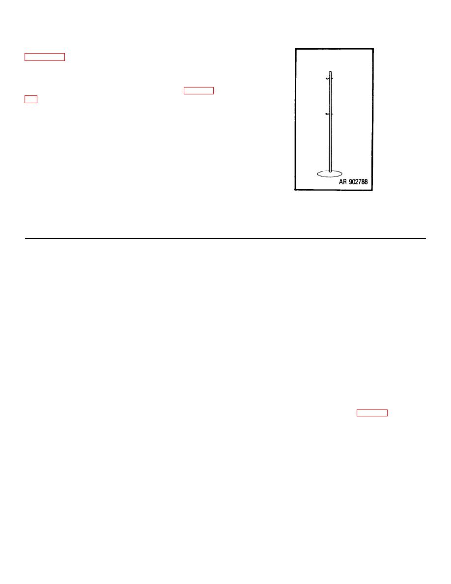
(2) The permanent reference point shown in
ground. Numbers placed on all sides of the pole permit
all-round identification. On temporary ranges, portable
reference points can be positioned in the impact area.
An example is the volleyball net pole shown in figure 2-
survey. The officer in charge of the OPs should
determine the azimuth to the reference point prior to the
conduct of the service practice. The battalion survey
party should provide the battalion S3 with a list of targets,
firing points and OPs, showing the coordinates and
altitudes of each to the nearest 0.1 meter. The list
should also reflect the target number and description for
ease of identification.
Figure 2-17. Temporary reference point
Here is a sample target list:
TGT
COORDINATES (M)
ALT (M)
DESCRIPTION
21
2168.1 3826.5
391
Self-propelled
gun
22
2207.4 3794.6
389
Red 8-inch propellant
container
23
2294.5 3788.2
392
Half
buried white
auto tire
Section II. SERVICE UPON RECIEPT OF EQUIPMENT
(4) Inspect all assemblies for excessive
2-4. General. When a new or reconditioned trainer is
wear, damage, missing parts or corrosion, proper
first received, it is the responsibility of the officer-in-
assembly, and correct adjustment. Inspect the safety
charge to determine whether the trainer has been
and all levers and locks for proper functioning.
properly prepared for service by the supplying
organization and whether it is in condition to perform its
(5) Check to see that trainer is complete with
mission.
all tools and equipment.
2-5. Inspecting and Servicing the Equipment.
(6) Clean and lubricate (Par. 3-4).
a. Inspect and service the trainer as follows:
2-6. Setting-up Instructions for the M31 Trainer.
(1) Remove trainer from shipping and
a. Assembly. The 14.5-mm trainer has four major
storage chest.
assemblies which are assembled in the following
sequence when emplacing the 14.5-mm trainer on the
(2) Remove volatile corrosion inhibiter.
tripod.
The four sections are packed in the
shipping[storage chest along with maintenance tools and
(3) Remove corrosion-preventive compound.
equipment. To set up the trainer follow steps 1 through
9.
2-12
|
|
Privacy Statement - Press Release - Copyright Information. - Contact Us |
