 |
|||
|
|
|||
|
Page Title:
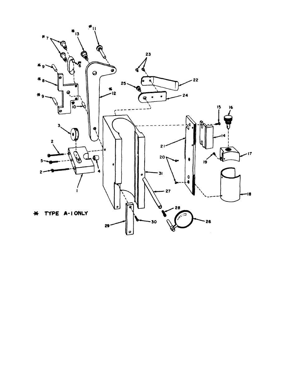
Figure 4-6. Disassembly of vernier slide assembly. |
|
||
| ||||||||||
|
|
 TM 9-6685-202-14
MI(C) 6685-202-14-4-6
Figure 4-6. Disassembly of vernier slide assembly.
head cap screws (2). Release locking nut (3) and clamp
d. Vernier Slide Assembly. Perform the following
bushing (4) by unscrewing socket head cap screw (5).
steps to disassemble the vernier slide assembly for
utilization of authorized replacement parts.
NOTE
Steps (3) through (5) below pertain to
(1) If it is desired to replace electrical lead, tip
the type A-1 only.
jack, or light bracket (17), unsolder electrical lead from
light bracket, otherwise leave solder in place.
(3) Remove correcting lever bracket spring
(6) secured by two correcting lever screws (7).
(2) Remove adjusting rod, clamping bracket
(1) from the side of vernier slide by removing socket
(4) Remove cam follower bracket (8) and
pins (9), (10), and (11) from correcting
4-16
|
|
Privacy Statement - Press Release - Copyright Information. - Contact Us |
