 |
|||
|
|
|||
|
Page Title:
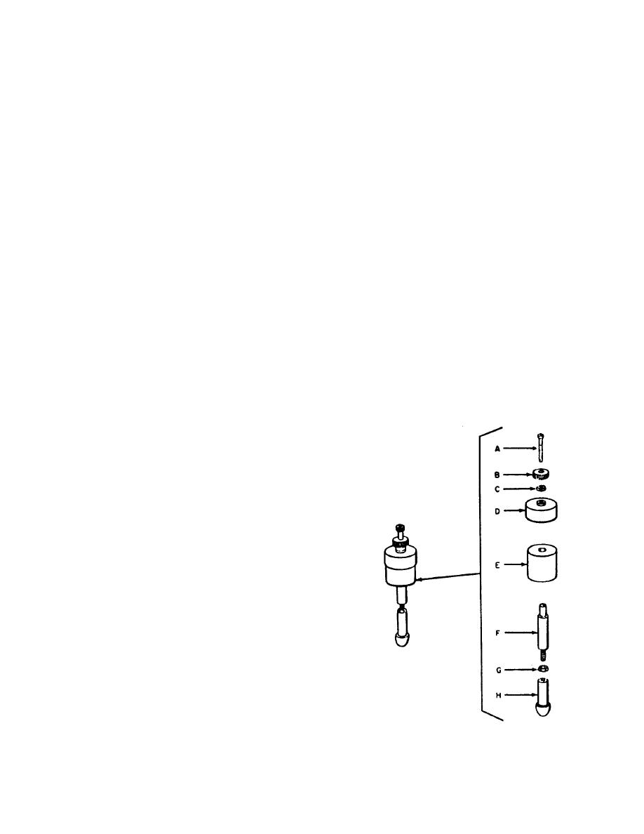
Figure 4-4. Disassembly of valve subassembly. |
|
||
| ||||||||||
|
|
 TM 9-6685-202-14
NOTE
(1) Remove evacuation manifold (1) and
Older barometers already in service
glass trap (47) by removing screw (2), clamps (3), and
nut on union (4).
use the thermometer rod as one
current path to the light bracket, and
(2) Remove top cap sleeve (5) by removing
the other members of the barometer
three socket head cap screws (6).
serve as a ground return. Therefore,
NOTE
in disassembling such models,
Do not remove top cap assembly
carefully preserve the three insulator
unless it is to be replaced.
washers
that
insulate
the
(3) Disconnect plastic tubing (7) from glass
thermometer rod from the top
stem on side of barometer tube.
mounting disc and the cistern base
(4) Unscrew tube evacuating nipple (8) from
which are in contact with the
top mounting disc (9).
grounded items. The light source tip
(5) Unlock barometer tube (10) by loosening
jack electrical lead on older models
gland nut on cistern base.
is attached by means of a terminal
(6) Lift barometer tube out of gland nut, slide
lug and screw to the bottom of the
tube through slot cut in top mounting disc (9), and
thermometer rod. In requisitioning a
remove from barometer.
replacement "light source tip jack"
(7) Remove top mounting disc (9) by
indicate the model of barometer
removing two socket head cap screws (11).
under repair.
(8) Free block (12) by removing setscrew
(21) Remove the thermometer rod (43) and
(13), socket head cap screw (14), and fat washer (15).
the scale rod (44) by removing the socket head cap
(9) Slide block off the scale rod.
screws (45) and (46) attaching the rods from the
(10) Remove cable clamp(16) by removing
underside of the cistern and base assembly.
socket head cap screw (17).
(22) The barometer is now disassembled into
(11) Unplug light source tip jack (18) from
its subassemblies which can in turn be further
receptacle on platform.
disassembled for utilization of authorized repair parts
(12) Carefully slip vernier slide assembly (19)
according to instructions in the following subparagraphs.
off the scale rod.
(13) Do not remove thermometer (22) or its
holder unless it is defective. If it is necessary to replace
the thermometer, remove thermometer holder (20) by
removing two socket head cap screws (21) and remove
thermometer from clay block inserts (23) in which it is
imbedded.
(14) On the type A-1, remove cam bar (24) by
removing cam bar stud (25) secured by socket head cap
screw (26) and flat washers (27) and (28).
(15) Remove scale (29) secured to scale rod
by two socket head cap screws (30) and flat washers
(31).
(16) Unscrew adjusting rod (32) from adjusting
bracket (33) and recover adjusting nut (34) and spring
washer (35).
(17) Remove adjusting bracket (33) by
removing socket head cap screw (36).
(18) Remove micrometer (37) from cistern lid.
(19) Remove gage block mount (38) by
removing two socket head cap screws (39).
(20) Separate cistern base assembly (40) from
platform assembly (41) by removing two socket head
cap screws (42) set in the top of the cistern base
assembly.
MI (C) 6685-202-14-4-4
Figure 4-4. Disassembly of valve subassembly.
4-12
|
|
Privacy Statement - Press Release - Copyright Information. - Contact Us |
