 |
|||
|
|
|||
|
Page Title:
ASSEMBLY AND PREPARATION FOR USE. (cont) |
|
||
| ||||||||||
|
|
 ARMY
TM 9-6650-235-13&P
MARINE CORPS
TM-08552A-13&P
CAUTION
The
M3
Borescope
must
be
supported to prevent bowing and
resultant damage. Refer to table 2-2,
supports required.
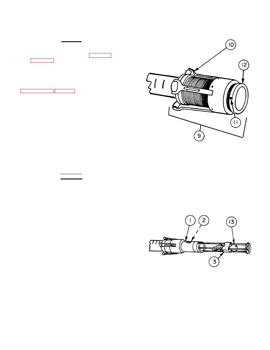
c. If using the 90-mm thru 8-inch support
assemblies (9), adjust to desired bore size by inserting
into muzzle end of cannon bore and adjusting as stated
in paragraph 2-2b, page 2-2. Then install supports on
objective tube assembly and borescope extension tubes
with support arms (10) facing away from end of tube
where illuminating head assembly attaches.
d. All supports should be installed in areas marked
SUPPORT AREA except for one support, which should
be installed immediately adjacent to illuminating head
assembly. When using more than one borescope
extension tube, alternate the support assemblies on the
support areas. Tighten the three screws (11) in body
(12) to secure supports to tubes.
e. If using 75-mm or 81-mm support assemblies,
install supports in locations noted above and tighten the
three setscrews to secure supports to tubes.
WARNING
The illuminating head assembly
presents a shock hazard if the M3
Borescope is not unplugged during
assembly.
f. Insert the illuminating head assembly (3) on the
end of the objective tube assembly (1) containing the
objective lens optical cell assembly (2). Ensure the
correct lamp (13) is installed.
2-13
|
|
Privacy Statement - Press Release - Copyright Information. - Contact Us |
