 |
|||
|
|
|||
|
|
|||
| ||||||||||
|
|
 ARMY
TM 9-6650-235-13&P
MARINE CORPS
TM-08552A-13&P
2-2.
CONTROLS AND INDICATORS (CONT).
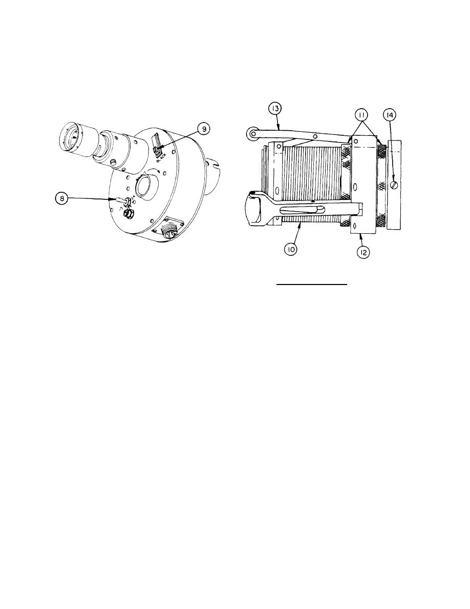
b. Support Assemblies. The 90-mm thru 8-in.
LATE MODEL
support assembly (10) is adjusted by two large knurled
nuts (11) located on each side of the rear ring (12) to
(6) Later models also have a double pole,
expand or retract the support arms (13) until the desired
double-throw toggle switch (8) to select either 115-volt or
bore diameter is achieved. In order to determine if the
24-volt operation, and the 24-V electrical power cord
proper diameter has been achieved, insert the support
adapter assembly is not required.
assembly in the bore of the weapon to be inspected.
After proper adjustment has been achieved, install the
(7) The blacklight lamp switch (9) is used to
support assembly (10) on the borescope and lock in
provide power to the illuminating head assembly. This
place with three screws (14).
switch is used by depot maintenance and also for
inspection of new cannon tubes by the manufacturer.
2-2
|
|
Privacy Statement - Press Release - Copyright Information. - Contact Us |
