 |
|||
|
|
|||
|
Page Title:
Instructions for Operating Lathes & Undercutter |
|
||
| ||||||||||
|
|
 TM 9 4940-462-14&P
Instructions for Operating Lathes & Undercutter
(Numbers in parenthesis indicate part numbers as shown on reverse side)
Remove shipping boards and mount on a substantial bench with a level top. FASTEN SECURELY with
four screws. A sub-base is advisable if bench is not level.
OILING:
Oil Undercutter Spindle (200) and Idlers (203) with light oil every time machine is used. Keep oil off the belt.
Oil Undercutter Base (208) sliding surfaces occasionally.
Oil chuck jaws and threads occasionally.
Always oil surfaces of armature shafts that come in contact with chuck jaws and thrust plugs (120).
TO MOUNT MOTOR: Bolt motor to base (130) so that motor pulley (134) will be on right hand side as you face the
machine. Belt tension adjusting post (132) should be at rear. Motor base fastens on rod (131) to rear of bed (100).
Rotation is Counter Clockwise when facing shaft extension.
TO PLACE ARMATURE IN MACHINE: Loosen thumb screws (119) holding Thrust Plugs of Chucks. Open chucks
sufficiently to receive ends of shaft, by turning outer chuck shells (115). Slip flat belt (136) over armature core and insert
armature shaft in Chucks. Loosen Tailstock Lock Nut (125). Move tailstock (123) so that Chuck Jaws are in line and ride
on bearing surfaces of shaft. Be sure the shaft surfaces that contact chuck jaws are free from any roughness, thus avoiding
damage to chuck jaws. Tighten Tailstock securely.
ADJUSTMENT OF CHUCKS: Adjust Chuck Jaws sufficiently tight so that when revolved by hand, armature has a slight
drag.
ADJUSTMENT OF THRUST PLUGS: Headstock Thrust Plug (120) is always adjusted to end of armature shaft so that
distance between end of commutator and face of chuck is sufficient to allow starting of cut. On late model armatures
the shaft is so short that this is not possible without the use of our No. 242 Double Cup Center. Cup center IS placed in
chuck and held by chuck jaws. Armature shaft with bearing removed is placed in smaller cup center. If bearing is not
removed, it may be placed in the larger cup center. (See catalog for other special adapters. ) Tailstock Thrust Plug is then
adjusted to opposite end of shaft to eliminate all end play. Lock both Thrust Plugs with Thumb Screws (1 19) in both
Head and Tailstock.
Tailstock Thrust Plug is always used when refinishing generator and most starter armatures. On some starters with
exceptionally long armature shafts, the Tailstock Thrust Plug is removed and armature shaft allowed to extend through the
Tailstock (123). End play is eliminated by moving Tailstock so that sides of Chuck Jaws rest against the shoulder of the
shaft.
MACHINING COMMUTATORS: Revolve armature by hand and be sure there is no end play before proceeding and that
armature has a slight drag. Position motor so that pulley (134) is opposite armature core. Place Blat Belt over armature
core and Pulley. With belt tension Adjusting Post, raise or lower motor to secure proper belt tension. This will best be
determined by experience, but in no case allow motor to be entirely supported by the belt. The Adjusting Post should
always be in contact with the bench. Loosen Tool Holder Lock Screw (1 12) slightly. Retract tool (111) by turning
Tool holder Feed Wheel ( 1 13) counter clockwise, so that it clears the commutator. Tighten Lock Screw ( 112) to prevent
toolholder (1 10) from turning in carriage block (109). There should be a slight drag on toolholder when adjusting for
depth of cut. Move Tool by turning Ball Crank (106) so that it is opposite the highest part of the commutator. Advance
Tool so that it just touches the highest part. Move Tool to right of commutator and advance it one numbered division on
graduated scale of Feed Wheel. Tighten lock Screw securely and machine commutator by turning on motor and turning
Ball Crank Handle slowly. Repeat, taking several light cuts, by advancing Feed Wheel another numbered division. For
finish cut advance tool 1/4 to 1/2 of one numbered division on hand wheel. It is customary to use 00 sandpaper after making
finish cut.
UNDERCUTTING COMMUTATORS: Adjust for depth of cut by turning vertical Adjusting Screw (219). Do not adjust
for too deep a cut. When adjusted for depth of cut, set lock screw (207). For B-10 Model only: remove Flat Belt and
position motor and line up so that Motor Pulley is directly opposite commutator. Mount Rubber Belt (211) so that it runs
from left side of Spindle Pulley (202) to underside of top idler (203), then to top of motor pulley (134), around motor
Pulley to underside of lower Idler (203), as shown in the illustration on back of this page. Adjust belt tension suitable for
cut.
CAUTION: Do not damage saw retaining screw (206) when changing saws, as it is a LEFT HAND SCREW.
TO REMOVE TOOLHOLDER (110): Loosen small Thumb Screw (113A) at left of carriage block (109). This releases
Feed Wheel, allowing Toolholder to be removed. Tool Bit (1 11) is removed from Toolholder by loosening Set Screw.
When placing Tool Bit back in Toolholder, make sure that top is parallel with the flat on top of the Toolholder AND
THAT TOOL BIT DOES NOT EXTEND MORE THAN 5/8" BEYOND TOOLHOLDER. Tighten Tool Bit Set Screw
securely and insert Toolholder in Carriage Block. Be sure the flat on the Toolholder is to the top.
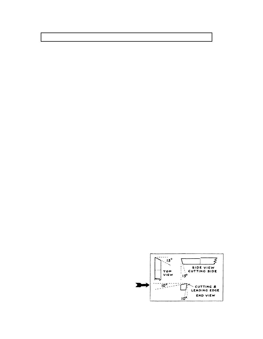
SHARPENING TOOL BIT (111): Tool Bit will be sharpened correctly
when shipped. Always keep it sharp to get the best results, MAIN-
TAINING SAME ANGLES AND CLEARANCES(see diagram). Keep
tool bit cool when grinding to prevent drawing temper. Any grinding
required should be done ONLY ON THE 15 DEGREE ANGLES AT THE
CUTTING END OF THE TOOL. The 10 degree angles should NOT BE
GROUND SINCE THEY ARE ALREADY GROUND TO A LENGTH
SUITABLE FOR THE LIFE OF THE TOOL.
1
Showing Correct Angles to Grind Tool Bit.
|
|
Privacy Statement - Press Release - Copyright Information. - Contact Us |
