 |
|||
|
|
|||
|
|
|||
| ||||||||||
|
|
 TM 9-4931-381-14&P-1
FRAME 1
INTERVAL
PROCEDURE
REFERENCE
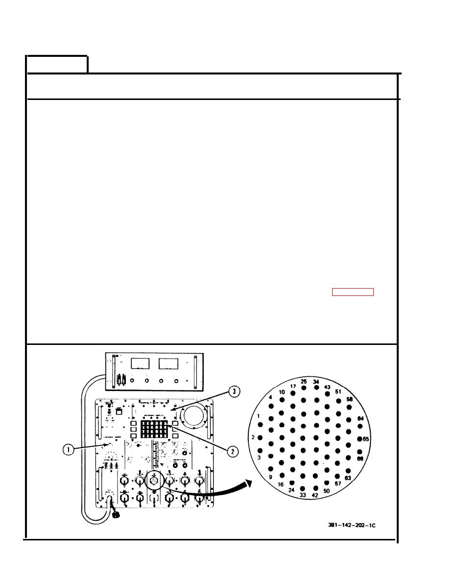
1.
Set THERMAL MODE switch (1) to ON. Press RESET (2).
NOTE
MESSAGE DISPLAY (3) must read:
THERMAL MODE-OFF
to measure reference voltage.
S
2.
Measure reference DC voltage at
connector J3, pin 65(+) and 66(-)
using digital multimeter. Measured
voltage must be 1.2 0.1 V dc.
If measured voltage is not
3.
Volume IV, para. 2-7,
4.450 0.020 V dc, digital
task 3.
voltmeter card A4.
S
Measure reference AC voltage at
4.
connector J3, pin 21 and 22, using
digital multimeter. Measured voltage
must be 13.00 0.5 V ac.
5.
If measured voltage is not
Volume Ill, figure 7-2.
14.00 0.03 V ac, perform PCU simulator
test (fail code 0.3.0.1).
END OF REFERENCE VOLTAGE
VERIFICATION CHECK
Volume II
2-2
Para. 2-2
|
|
Privacy Statement - Press Release - Copyright Information. - Contact Us |
