 |
|||
|
|
|||
|
Page Title:
Section II. PHYSICAL DESCRIPTION |
|
||
| ||||||||||
|
|
 Section Il. PHYSICAL DESCRIPTION
2-3.
G e n e r a l . The test set consists of the thermal system test controller (TSTC), the
accessory case, the thermal sight coIIimator, the head/gunner/TRU holding fixture, and the
commander's display holding fixture.
a.
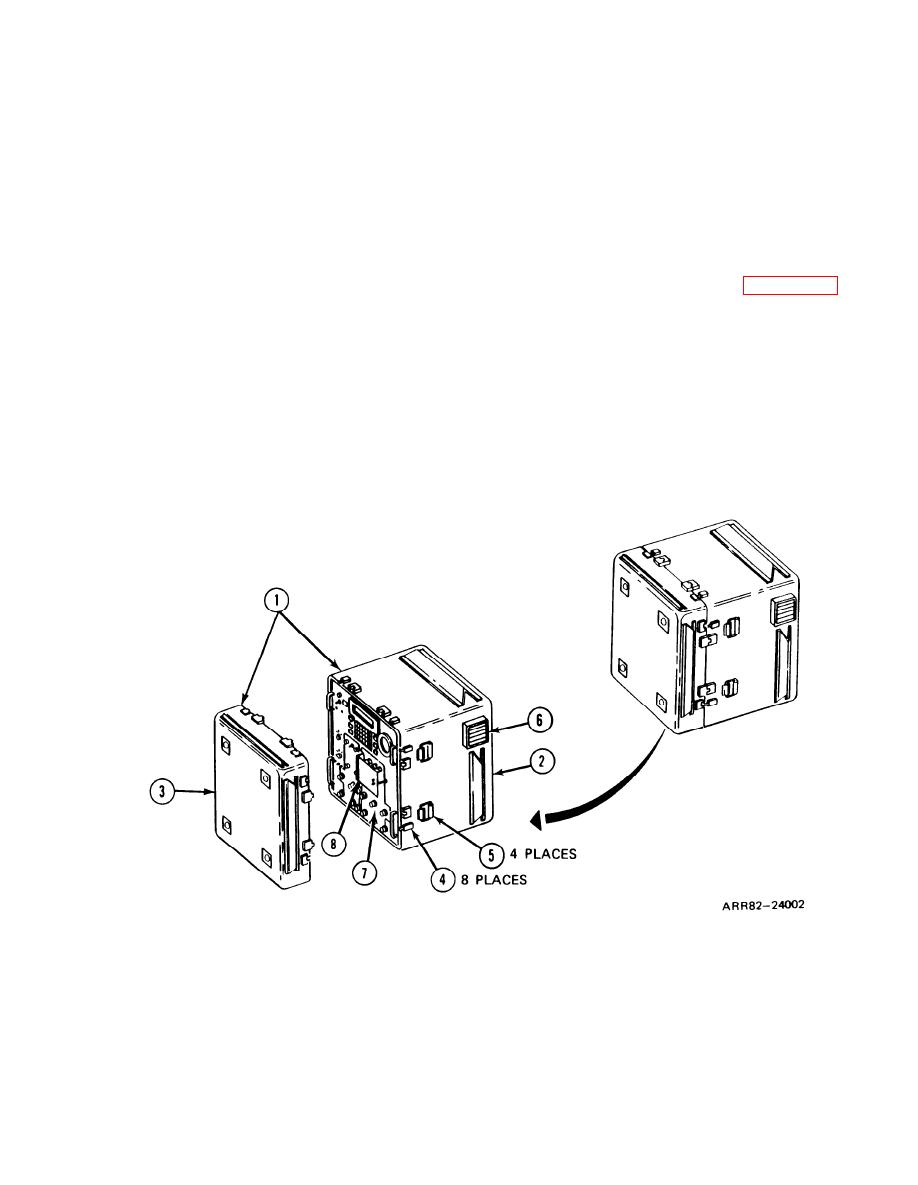
Thermal System Test Controller (figure 2-2). The TSTC is contained in a portable
case assembly ( I ). The case assembly (I) consists of a case (2) and case cover (3) which are
joined by eight latches (4). When the cover (3) is in position and the latches (4) are closed, the
case assembly ( I ) is sealed. Four handles (5) on the case (2) permit easy handling. There is also
a fan assembly (6) built into the TSTC case (2). This fan (6) is used to cool the test set. For
TSTC national stock number refer to the components of end item list in volume 1, appendix B.
When the eight latches (4) on the case assembly are unsealed, the case cover (3) may be
removed, exposing the TSTC front panel (7). All TSTC controls, switches, indicators, and test
cable connectors are mounted on the front panel (7). In the center of the front panel (7) there
is a hinged flap (8) which is used to cover either the TIS or the TTS controls. If the operator is
working on the TIS controls, he covers the TTS controls. If the operator is working on the TTS
controls, he covers the TIS controls.
Figure 2-2. Thermal System Test Controller
Volume I
2-5
Para. 2-3
|
|
Privacy Statement - Press Release - Copyright Information. - Contact Us |
