 |
|||
|
|
|||
|
|
|||
| ||||||||||
|
|
 TM 9-4910-736-14&P
Troubleshooting Guide. Consult the troubleshooting guide (table 3-2)
d.
and from the trouble symptom determine the probable cause and the
action that should be taken. These are usually fault-isolating, voltage
measurement checks given in tables 3-3 through 3-11. Use the test set
schematic diagram (figure FO-1) as an aid in troubleshooting.
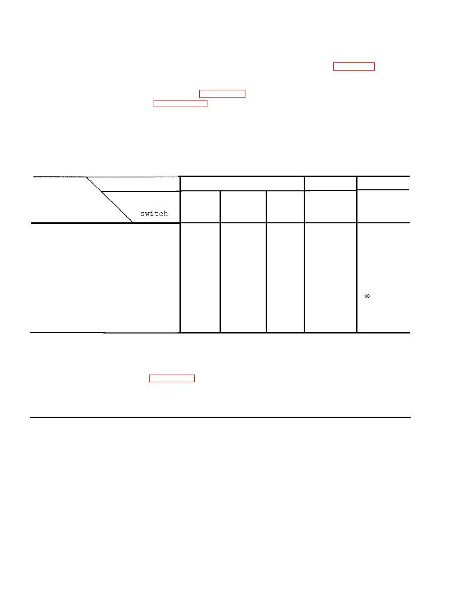
Resistance Chart
NOTE
Disconnect battery from unit and measure DC resistance as specified.
COIL
FUNCTION switch
COND
OHM
Resistance
between
SERIES
CAP
RES
points
LEAK
0 ohms
-12 V lead and pin E22
/
/
/
/
/I
-12 V lead and pin E19
0 ohms
/
/
/
+12 V lead and pin El
0 ohms
0 ohms
/
0 ohms
/
+12 V lead and test lead
with red boot
ohms
/
/
/
/
Test lead with black boot
and pin E22
0 ohms
0 ohms
/
/
/
NOTE
If all resistance measurements are normal, consult trouble
shooting guide (table 3-2) for further action.
If any resistance measurements are abnormal, inspect the
defective line to locate the interruption.
|
|
Privacy Statement - Press Release - Copyright Information. - Contact Us |