 |
|||
|
|
|||
|
Page Title:
Installation of Mounting Legs and Oil Drain Tube. |
|
||
| ||||||||||
|
|
 TM 9- 2990- 205- 34&P
-
-
-
ASSEMBLY AND OPERATIONAL TESTING - CONTINUED
-
0012 00
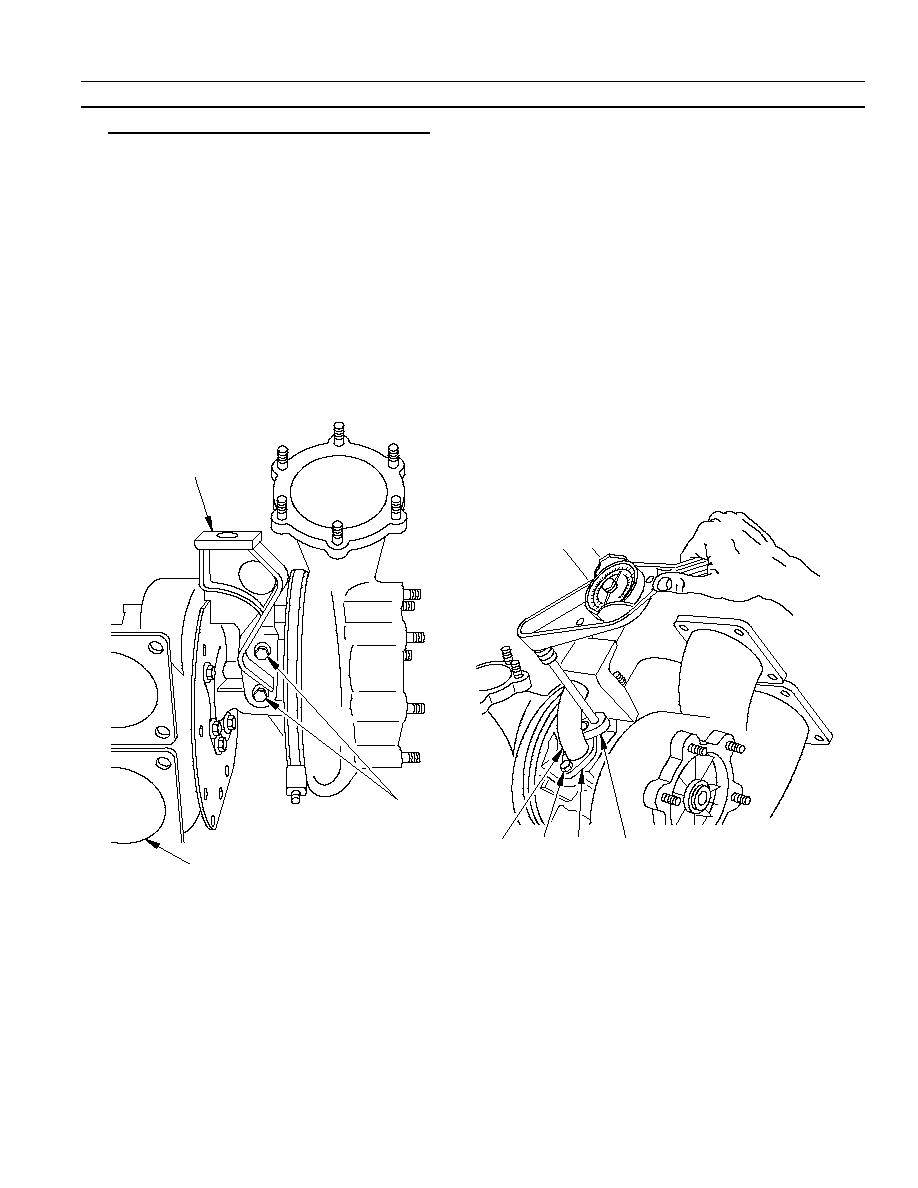
9. Installation of Mounting Legs and Oil Drain Tube.
NOTE
The mounting leg on the same side as the turbine housing exhaust inlet is referred to as the
"inner" mounting leg and must be installed first.
a. Install inner mounting leg (1) and secure with two cap screws and new lockwashers (2).
b. Torque cap screws to 230 to 250 lb--in (25.99 to 28.25 NSm).
c.
Install new gasket (3) and oil drain tube (4). Secure with two cap screws and new lockwashers (5).
NOTE
The oil drain tube must pass through the opening in the INNER leg. The oil drain tube must
always be on the same side as the turbine housing exhaust inlet.
d. Torque cap screws to 230 to 250 lb--in (25.99 to 28.25 NSm) using crowfoot attachment (6).
1
2
4
5
3
6
TURBINE EXHAUST
INLET
03i500m
0012 00- 13
-
|
|
Privacy Statement - Press Release - Copyright Information. - Contact Us |
