 |
|||
|
|
|||
|
Page Title:
Inspection of Turbine Wheel and Shaft Assembly. |
|
||
| ||||||||||
|
|
 TM 9- 2990- 205- 34&P
-
-
-
INSPECTION OF COMPONENT PARTS - CONTINUED
-
0010 00
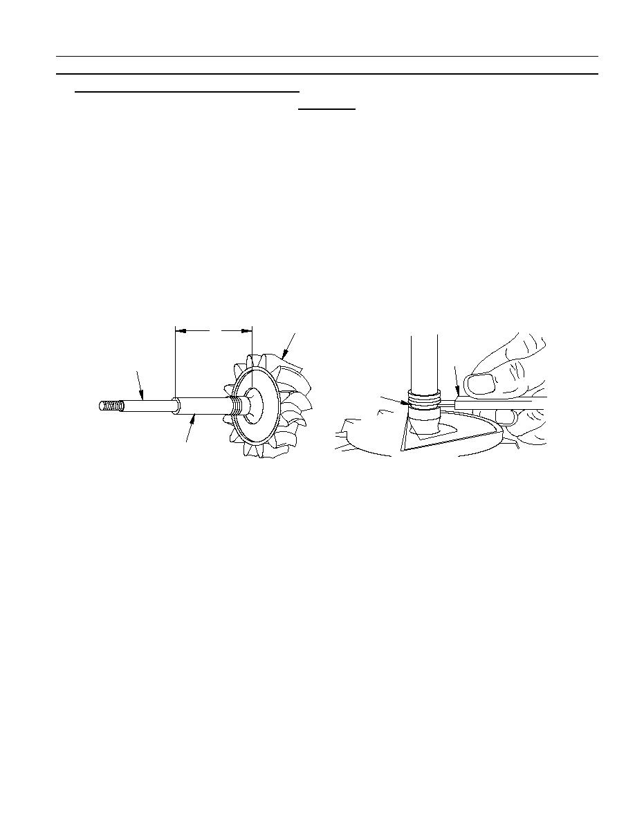
3. Inspection of Turbine Wheel and Shaft Assembly.
CAUTION
It is important to use extra care when checking for cracked blades. If undetected, they could
break during operation and cause severe damage.
a. Inspect turbine wheel and shaft assembly (1) for bent, cracked, broken, or missing blades, or a bent shaft.
b. Using micrometer, check the diameter of the thrust area (2) of the shaft. The measurement must be from
0.5000 inch to 0.4997 inch.
c.
Using micrometer, check the length of the shaft (3) from thrust surface shoulder to inner face of turbine wheel.
This measurement must be from 3.9860 inches to 3.9820 inches.
d. Using micrometer, check the diameter of the bearing area of the shaft (4). This measurement must be from
0.6865 inch to 0.6862 inch.
e. Inspect metal seal ring groove (5) for wear using gage (6). If "NO--GO" end of gage enters the ring groove,
replace the turbine wheel end shaft assembly.
f.
Replace the turbine wheel and shaft assembly if damaged or if it does not meet the wear standards specified
in the preceding steps.
1
3
6
2
5
4
03i476m
0010 00- 3
-
|
|
Privacy Statement - Press Release - Copyright Information. - Contact Us |
