 |
|||
|
|
|||
|
Page Title:
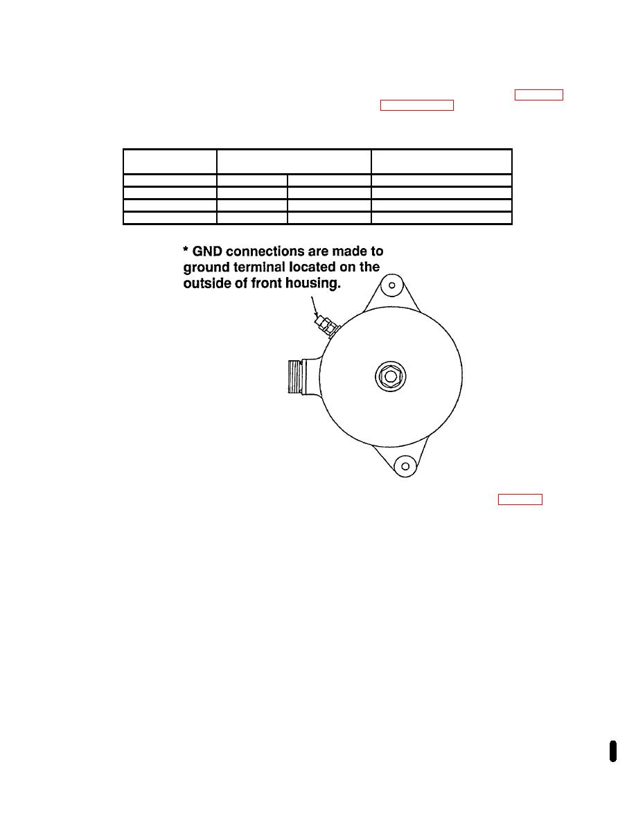
Table 2-6. OUTPUT PLUG CONTINUITY |
|
||
| ||||||||||
|
|
 TM 9-2920-257-30&P
(4) Electrical Continuity Check - Set ohmmeter to X10 scale and make sure ohmmeter is zeroed. Check
the generator connector pins to insure all internal wiring is intact. Check output plug continuity (refer to table 2-6). If any
reading is out of limits, replace generator front housing, in accordance with paragraph 3-4b, steps 1 thru 17.
Table 2-6. OUTPUT PLUG CONTINUITY
Generator Output Plug
Expected
Scale
Readings
X 10K
PIN
B
GND *
Very High
X1
PIN
B
PIN C
ZERO
X1
PIN
B
PIN D
Very High
X 10K
PIN
E
GND *
Very High
(5) Diode heat sink tests - Remove all phase leads (P1-P6) from front housing (fig 2-14). Check the
diode heat sink assembly using a diode tester. If diode tester is used, refer to manufacturers' instructions for proper
connections. If a diode tester is not available, use a multimeter and the following procedures.
CAUTION
To prevent damage to the diodes, do not use an AC device, such as a leakage
tester to check the diode heat sink.
NOTE
Do not allow sleeves on leads to slide down leads.
Phase terminals without
sleeves can short to alternator body.
NOTE
Heat sink diodes are de-rated for heavy duty performance. If diode failure is
detected, examine the entire charging system for loose connections. If a diode
failure is indicated, suspect stator failure as well.
Change 1 2-21
|
|
Privacy Statement - Press Release - Copyright Information. - Contact Us |
