 |
|||
|
|
|||
|
|
|||
| ||||||||||
|
|
 (2) Connect one of the posts of a 24-volt
(3) Remove solenoid lead assembly con-
battery to the battery solenoid terminal.
necting battery switch terminal stud and
Connect the other battery post to the
battery solenoid terminal.
motor solenoid terminal.
(4) Connect a 24-volt battery supply to bat-
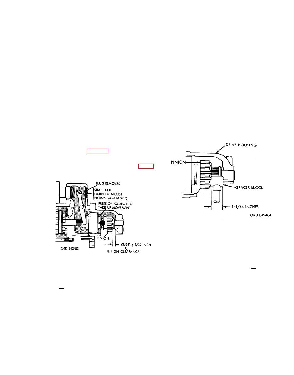
(3) Place a 1-1/64-inch spacer block (fig.
tery solenoid terminal and motor sole-
39) between the pinion and drive housing
noid terminal.
and momentarily hold a jumper lead
from the motor switch terminal stud to
(5) Momentarily hold a jumper lead from
the motor solenoid terminal. The pinion
the motor switch terminal stud to the
will now shift against the spacer and
motor solenoid terminal. The pinion
remain so until the jumper lead is dis-
will now shift into cranking position and
connected.
remain so until the battery is discon-
nected.
(6) Push pinion back toward armature to
take up slack movement.
(7) Remove inspection plug and gasket (B
and A, figure 7, step 1) and measure
the distance between pinion and drive
housing and adjust clearance to 23/64
1/32-inch by turning shaft nut (fig. 38).
FIGURE 39. PINION BLOCK TEST.
(4) An open circuit should be indicated be-
tween the battery switch and motor
switch terminals. If continuity exists,
decrease the pinion clearance (a above)
PINION CLEARANCE.
to the minimum limit of 21/64-inch and
then recheck to make sure an open cir-
cuit now exists.
b. Perform pinion block check as described
below.
(5) Disconnect battery and test equipment
and install motor field connector, ground
(1) Connect a test light or other continuity
lead, and solenoid lead.
checker between the battery switch ter-
minal stud and motor switch terminal
stud.
(6) Install plug and gasket.
|
|
Privacy Statement - Press Release - Copyright Information. - Contact Us |
