 |
|||
|
|
|||
|
Page Title:
Figure 42. Adjusting bolt turned in. |
|
||
| ||||||||||
|
|
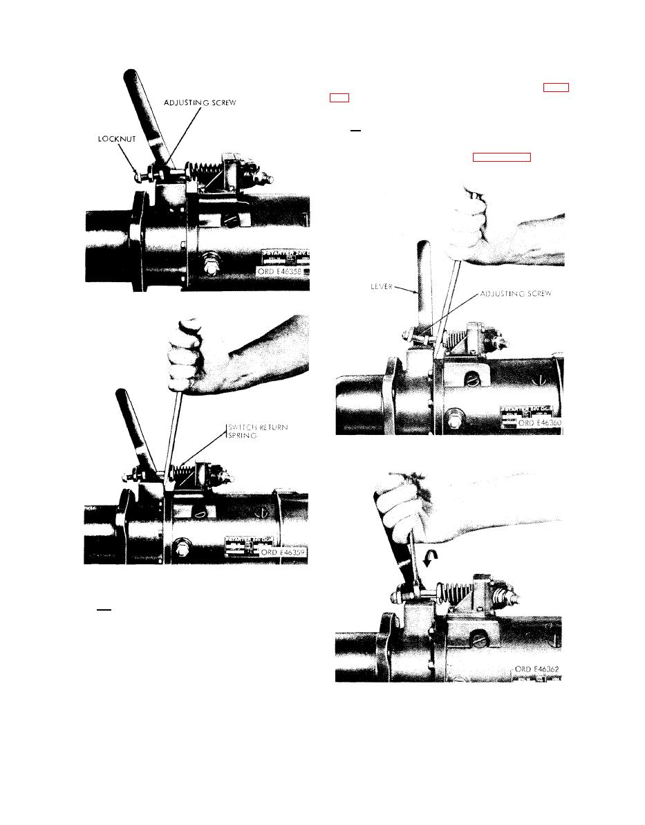 Note. In proper operation the lever
and shaft assembly moves freely from
initial to near vertical position.
If
any stickiness or binding is felt, the
lever and shaft must be removed (fig.
14) and the shaft lubricated with grease,
Specification
MIL-G-3278.
d. With switch engaged and
lever po-
sitioned, turn adjusting bolt
out until
the bolt head rests against the
blade and
plunger rod as shown in figure
Figure 42. Adjusting bolt turned in.
Figure 44. Head of adjusting bolt resting
against blade and plunger rod.
Figure 43. Compressing spring
to engage switch.
c . While holding switch in engaged
position, pull lever forward until posi-
tork drive comes to rest against collar
and pinion stop. At this point the lever
is in a near vertical position.
Further
movement of lever causes the 30 lb drive
spring to compress. Do not compress the
drive spring.
Figure 45. Turning
adjusting
bolt.
|
|
Privacy Statement - Press Release - Copyright Information. - Contact Us |
