 |
|||
|
|
|||
|
|
|||
| ||||||||||
|
|
 (2) Inspect the yoke for wear in the
(4) Inspect armature shaft aline-
shaft hole and wear on the slider
ment and commutator for ec-
blocks.
Replace the yoke if
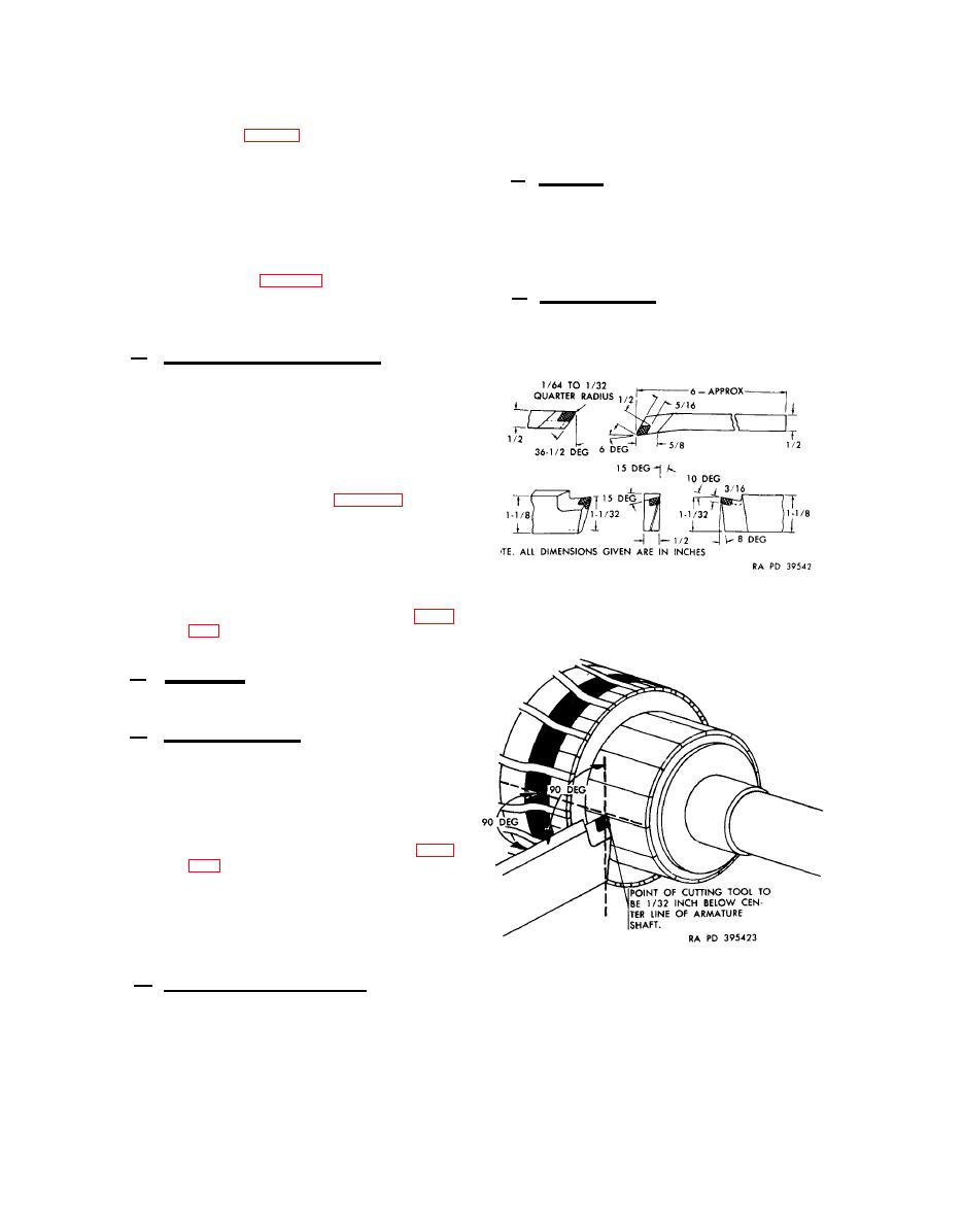
centricity to shaft with a lathe
or "V" blocks and a dial indi-
wear exists.
cator (fig. 31). Check armature
27. R e p a i r
shaft for true alinement. If
shaft run out exceeds 0.005-
a.
inch, armature must be re-
General.
The following subpara-
If commutator eccen-
graphs cover only those parts wherein a
placed.
repair operation will return the damaged
exceeds 0.003-inch,
tricity
commutator of armature shaft
part to serviceable condition. Parts not
must be refinished provided it
detailed herein must be replaced when they
fail to pass the required inspection (par.
will not be cut below limits
specified in repair and rebuild
26).
If com-
standards (par. 40).
b. Pinion Housing. Minor burs or dam-
mutator requires cutting below
age on the mating ,surfaces of the pinion
limits specified, replace arm-
housing can be removed or cleaned up with
ature.
a fine mill file.
Head and Bushing Assembly.
h.
Inspect the commutator end head
(1)
for cracks, distortion, and
burs. Replace if damaged.
Inspect the head bushing-type
(2)
bearing for score marks and wear
patterns. Check bearing against
limits specified in repair and
rebuild standards (par. 40) and
replace using a 0.750-inch ar-
bor if worn beyond limits.
If head bushing-type bearing is
(3)
removed, check diameter of bear-
ing bore in commutator end head
Figure 32. Cutting tool
against limits specified in re-
sharpening dimensions.
pair and rebuild standards (par.
not within these limits.
i. End Cover. Inspect the end cover
for dents, cracks, and distortion. Replace
if damaged.
i. Switch Assembly.
(1) Inspect the switch body for
cracks, distortion, and burs.
Replace if damaged.
(2) Check plunger rod return spring
against limits specified in re-
pair and rebuild standards (par.
return
spring if it is not within these
limits.
(3) Inspect the switch blade hous-
ing for cracks, distortion, and
burs. Replace if damaged.
Figure 33. Proper position of
cutting tool.
k.
Shifting Lever and Yoke.
(1) Inspect the shifting lever for
wear on the shaft and burs in
Replace
the packing groove.
the lever if worn or damaged.
|
|
Privacy Statement - Press Release - Copyright Information. - Contact Us |