 |
|||
|
|
|||
|
Page Title:
Figure 5. Removing or installing switch blade housing and associated parts. |
|
||
| ||||||||||
|
|
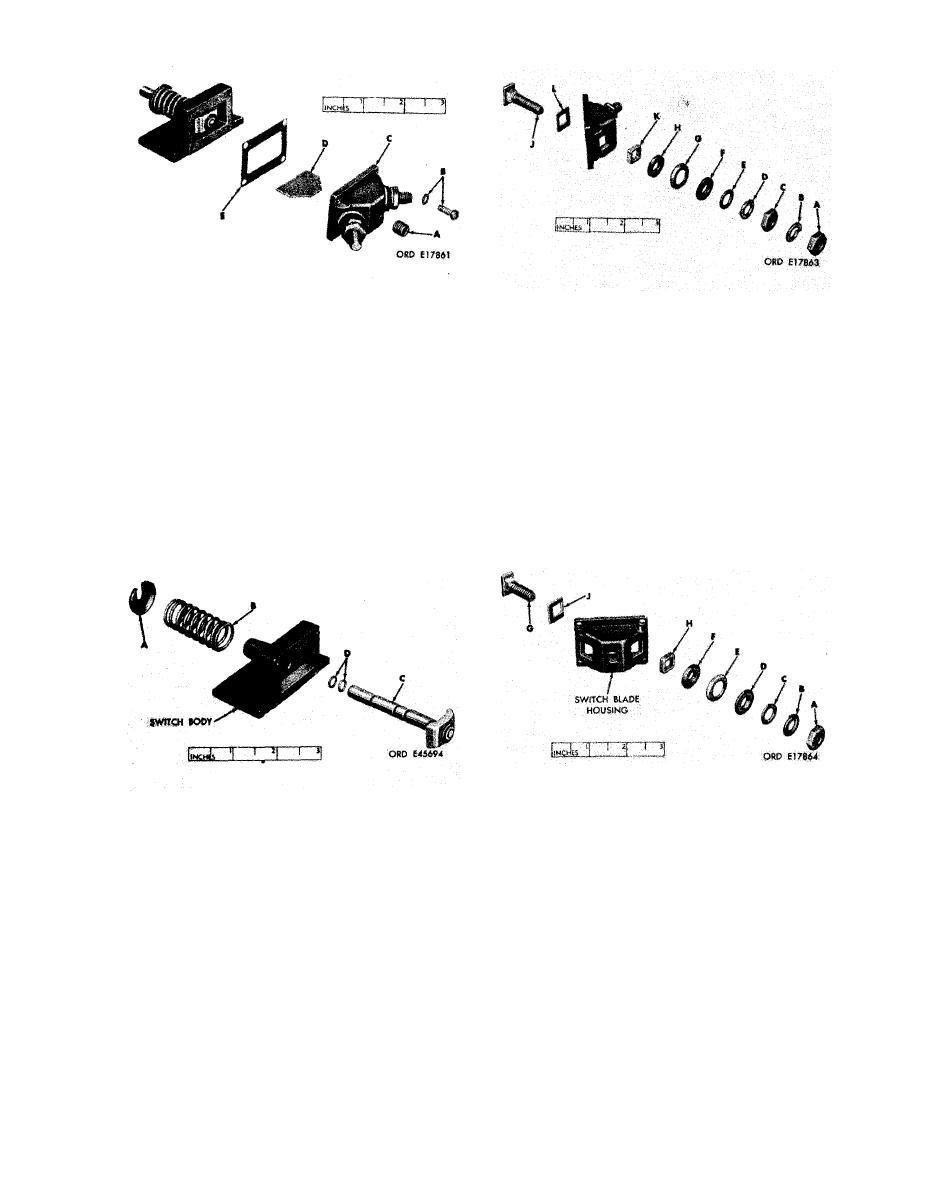 A - Remove housing plug.
Hex nut
A
-
B
-
Lock washer
Hex nut
c
-
B - Remove four screws and lock washers.
D
-
Lock washer
E
-
Terminal washer
c - Remove switch blade housing and as-
F
-
Terminal bushing
sociated parts.
G
-
Gasket retainer
H
-
Terminal gasket
D - Remove two housing insulators.
J
-
Long contact terminal
K
-
Insulating,bushing
E - Remove and discard switch body gas-
L
-
Insulating washer.
ket.
Figure 7.
Removing or installing long
contact terminal and associated parts.
blade housing and associated parts.
Hex nut
A
-
remove
and
A - Depress return spring
B
-
Lock washer
spring retainer.
Terminal washer
c
-
Terminal bushing
D
-
B - Remove return spring.
Gasket retainer
E
-
Terminal gasket
F
-
c - Remove blade and plunger rod.
Short contact terminal
G
-
Insulating bushing
H
-
D - Remove and discard plunger rod pack-
Insulating washer
J
-
ings.
Figure 8. Removing or installing short
Figure 6. Removing or installing blade
contact terminal and associated parts.
and plunger rod and associated parts.
11
|
|
Privacy Statement - Press Release - Copyright Information. - Contact Us |
