 |
|||
|
|
|||
|
Page Title:
Disassembly Brush Holder Assembly. |
|
||
| ||||||||||
|
|
 TM 9- 2920- 232- 34&P / TO 38X14- 2- 32
-
-
-
- -
DISASSEMBLY OF THE STARTER ASSEMBLY - CONTINUED
-
0008 00
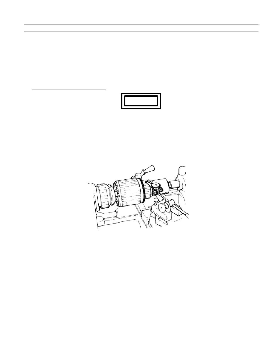
d. Commutator diameter on armature must be within 2.3080 to 2.3180 inches. Inspect armature shaft and
commutator for eccentricity with a lathe or "V" blocks and a dial indicator. If the eccentricity exceeds 0.0050
TIR, the commutator must be resurfaced provided it will not be cut below 2.1930 inch diameter limits.
e. Inspect armature shaft splines for wear. Replace the armature if the splines are defective.
f.
Inspect the commutator contact surface. A satisfactory condition is indicated by an even, highly burnished,
dark--copper color. If the contact surface is rough, pitted, scored, burned, or coated with hard carbon or oil,
the commutator must be resurfaced. If mica is not 0.025 to 0.032 inch below surface of commutator, it must
be undercut to the correct depth.
4. Disassembly Brush Holder Assembly.
WARNING
Compressed air used for cleaning purposes will not exceed 30 psi. Use only with effective
chip guarding and personal protective equipment (goggles/shield, gloves, etc.).
NOTE
When disassembling a 12--brush starter and conversion to 6--brush will be made at assembly,
do not disassemble brush holder assembly.
a. Remove buildup dust and dirt using compressed air prior to test.
0008 00- 9
-
|
|
Privacy Statement - Press Release - Copyright Information. - Contact Us |
