 |
|||
|
|
|||
|
Page Title:
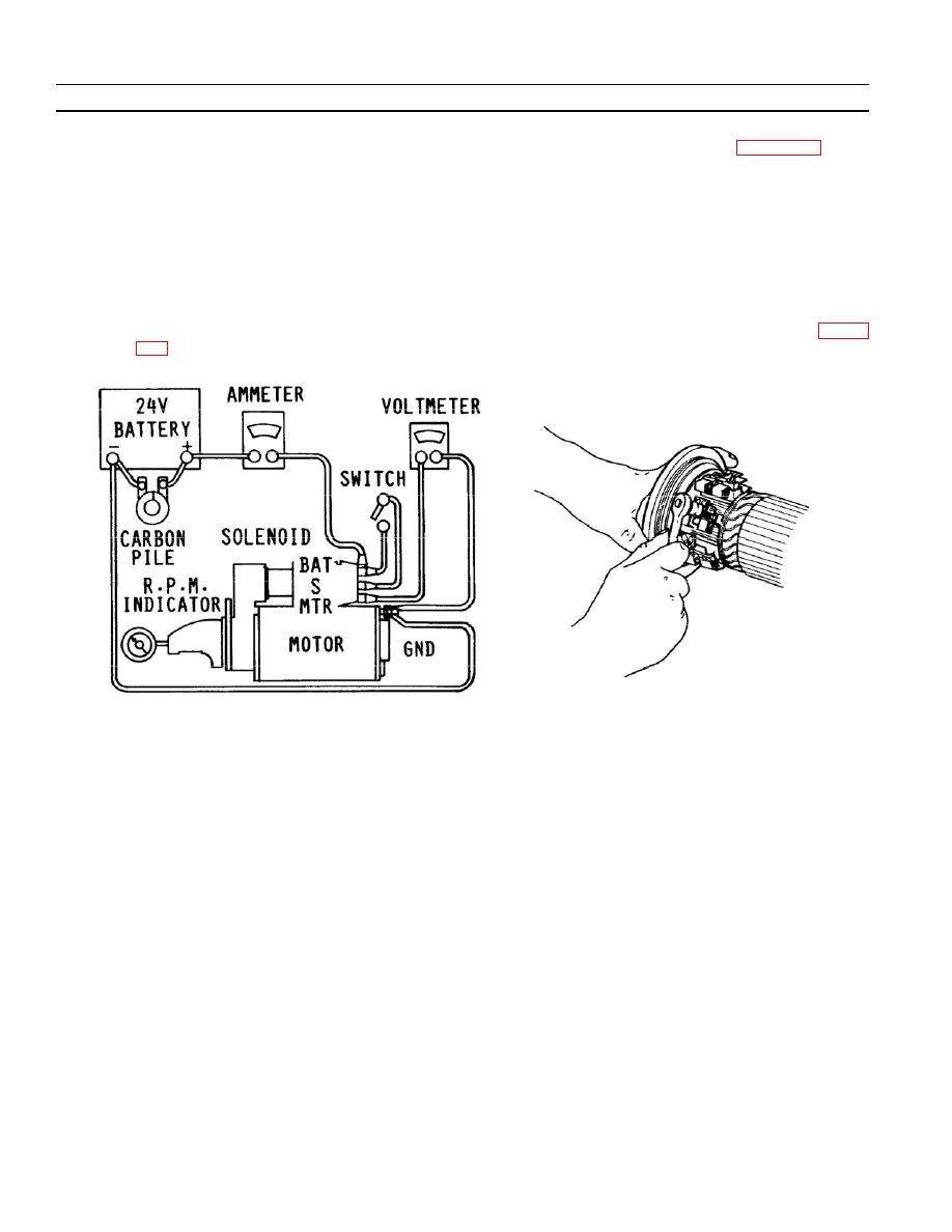
Figure 2--3. No--Load Test Circuit |
|
||
| ||||||||||
|
|
 TM 9- 2920- 232- 34&P / TO 38X14- 2- 32
-
-
-
- -
TROUBLESHOOTING INSTRUCTIONS - CONTINUED
-
0005 00
3) No--Load Speed and Current. Connect starter to power supply with circuit equivalent to Figure 2--3. When
the switch is closed, the armature should rotate at 5500 to 7500 rpm and current should be in the range of
95A to 120A when applied voltage is at least 20 VDC.
NOTE
Voltage higher than 20 VDC will cause higher rpm in cause a
starter, but current draw will remain about the same because
counter--electromotive force (CEMF) will increase.
4) Brush Lead Tightening. Low speed and low current are a symptom of high internal resistance which may
be caused by loose attaching screws for brush leads. Torque loose brush lead screws as shown in Figure
0005 00- 2
-
|
|
Privacy Statement - Press Release - Copyright Information. - Contact Us |
