 |
|||
|
|
|||
|
|
|||
| ||||||||||
|
|
 TM 9- 2920- 232- 34&P / TO 38X14- 2- 32
-
-
-
- -
TROUBLESHOOTING INSTRUCTIONS
THIS WORK PACKAGE COVERS:
Troubleshooting Instructions and Malfunction/Corrective Action Table
TROUBLESHOOTING INSTRUCTIONS
a. General. The troubleshooting procedures check for improper operation as reported and helps find defective
components. These procedures are also used when malfunction is not specified to determine the kind of
repair needed.
1) Probable causes and corrective actions for most starter malfunctions are listed in Table 2--1. Probable
causes for each malfunction are listed from most probable to least probable.
2) When condition of a starter is unknown, specific malfunctions can be looked for in the sequence
presented by Table 2--1. Whether a malfunction is found in this manner or by verification of a reported
failure, the corrective action should be taken before further operation of the starter, which might increase
damage. Only the more common malfunctions are listed in Table 2--1.
b. Troubleshooting Procedure. If a specific malfunction described can be found in Table 2--1, verify and
determine the actual cause. Partial disassembly and/or specific tests may be required as noted by the
column entries for that malfunction. Correct defects as applicable.
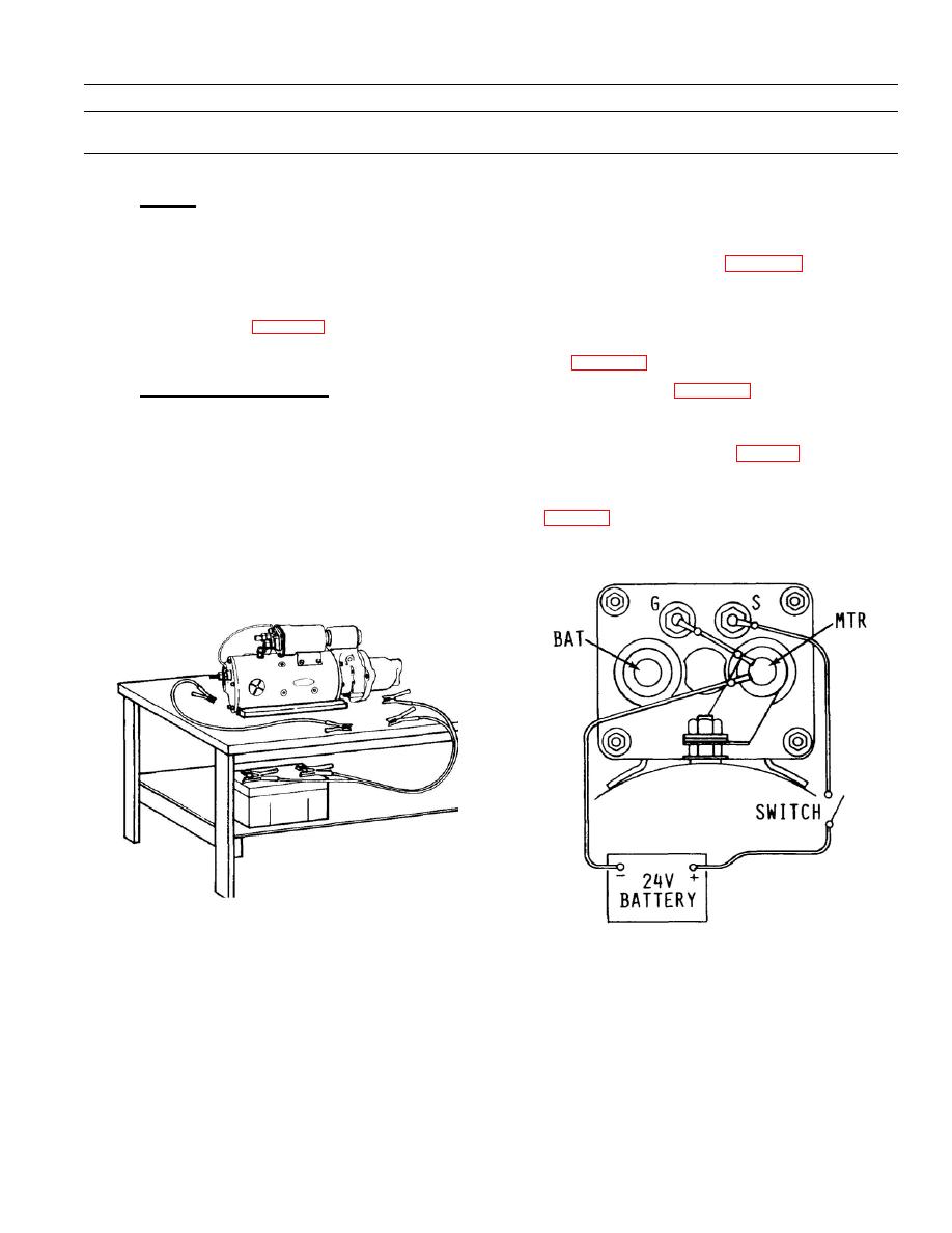
1) Test Stand Operation. With the starter supported on a suitable test bench or stand (fig. 2--1), check
armature for freedom to rotate by prying on drive pinion as necessary to turn armature counterclockwise
as viewed from drive end.
2) Solenoid Shift Check. Connect power source or battery (fig. 2--2) to the solenoid terminals as indicated.
Briefly close, then open the switch. Drive clutch assembly should shift in response to switch closure and
return when switch is opened.
0005 00- 1
-
|
|
Privacy Statement - Press Release - Copyright Information. - Contact Us |
