 |
|||
|
|
|||
|
Page Title:
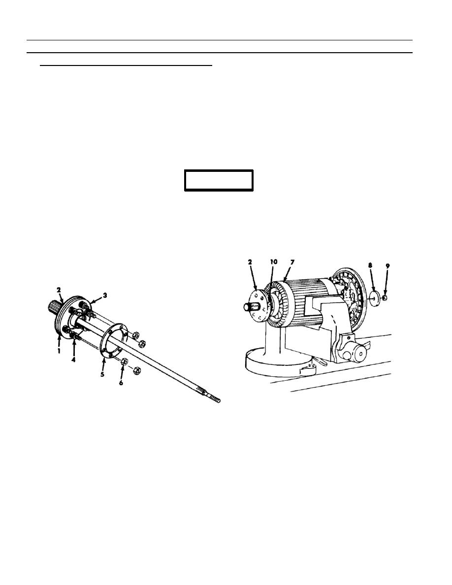
Generator Drive Shaft Subassembly and Adjustment. |
|
||
| ||||||||||
|
|
 TM 9- 2920- 224- 34&P
-
-
-
ASSEMBLY OF THE GENERATOR - CONTINUED
-
0010 00
6. Generator Drive Shaft Subassembly and Adjustment.
a. Apply a thin film of light grease to both sides of dampener generator plate (1), surfaces that contact plate on
flange of inner shaft assembly (2), and spring backup dampener generator plate (3).
b. Place dampener generator plate (1) on inner shaft assembly (2) studs with alignment mark on edge of plate
between the two marks on edge of shaft assembly (2) flange.
c.
Place other dampener generator plate (3) on shaft assembly (2) studs with spring--pocket side (counterbored)
away from plate (1).
d. Place one compression helical spring (4) on each stud. Install spring packing retainer (5) and six new
self--locking nuts (6). Tighten each nut evenly until stud protrudes slightly through nut.
e. Adjust drive shaft damper mechanism as follows:
CAUTION
Using excessive clamping pressure when armature is
clamped in vise will damage armature core. Tighten vise
jaws no more than necessary to hold armature against
applied torque.
f.
Put armature (7) in a soft--jawed vise and clamp just tight enough to resist torque to be applied.
0010 00- 14
-
|
|
Privacy Statement - Press Release - Copyright Information. - Contact Us |
