 |
|||
|
|
|||
|
Page Title:
Tube Axial Fan and Adapter Generator (10889713). |
|
||
| ||||||||||
|
|
 TM 9- 2920- 224- 34&P
-
-
-
ASSEMBLY OF THE GENERATOR - CONTINUED
-
0010 00
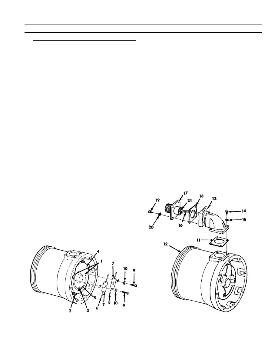
3. Tube Axial Fan and Adapter Generator (10889713).
NOTE
Continuity of lead to negative brush holder can be
checked with a multimeter on Rx1 scale.
a. Position fan motor leads for connection to respective capacitors so that lead (1) from negative brush holder
(2) lays clockwise from exit hole grommet (3) in fan motor (4).
b. Ensure one--inch long insulating sleeves (5) are on each motor lead (1) and slid back against grommet (3)
during soldering. Connect lead (1) from negative brush holder (2) to terminal (6) on capacitor (7) by soldering.
c.
Connect remaining motor lead (1) to terminal (8) of remaining capacitor (7) by soldering.
d. When solder has cooled, slide insulating sleeves (5) over soldered connections.
e. Install each capacitor (7) at its respective position on fan motor (4) with machine screw (9) and new
lockwasher (10). Torque to 3.5--4.5 Ib--in (0.4 to 0.5 Nm).
f.
Place new gasket (11) in position on fan housing (12). Place contact electrical shell (13) in position and
secure on fan housing with four machine screws (14) and new lockwashers (15). Torque to 3.5--4.5 Ib--in (0.4
to 0.5 Nm).
g. Insert sleeved wire leads (16) attached to electrical receptacle connector (17) through new gasket (18) and
shell (13). Position gasket (18) and connector (17) so indexing key in connector is on side farthest from fan
housing and install four machine screws (19) and new lockwashers (20). Torque to 3.5--4.5 Ib--in (0.4 to 0.5
Nm).
h. Ensure lead wires (16) from connector (17) are identified and routed to proper capacitors. Lead (16) from
connector pin B (21) must be routed to capacitor (7) which is connected to negative brush holder (2) of fan
motor (4).
0010 00- 7
-
|
|
Privacy Statement - Press Release - Copyright Information. - Contact Us |
