 |
|||
|
|
|||
|
|
|||
| ||||||||||
|
|
 TM 9- 2920- 224- 34&P
-
-
-
THEORY OF OPERATION - CONTINUED
-
0003 00
c.
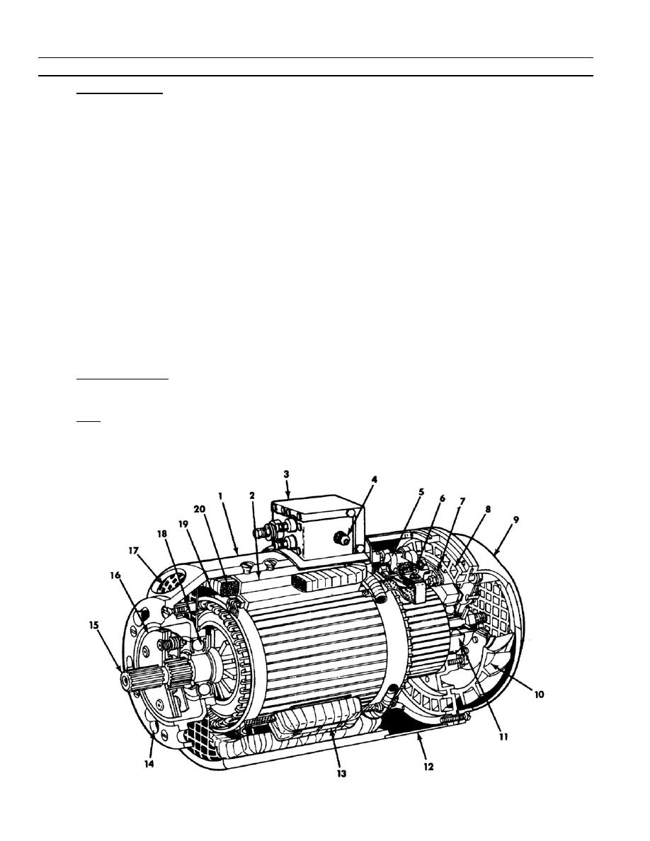
Power Generation. When armature (19) turns, an electrical charge is produced as armature coils cut the
magnetic lines of force around the generator's field coils (20). The electricity produced is conducted from the
armature windings to the commutator where it is collected by the brushes and delivered to output terminals
and noise suppression capacitors. These capacitors minimize stray currents which could interfere with
communications equipment operating within the vicinity of the generator.
1) DC voltaqe applied across A and E terminals on--filter assembly (3) causes a current flow in the shunt
winding which produces a magnetic field with six poles. Three N poles and three S poles are generated
by the current flow and these poles are positioned so that each armature coil must cut six fields of
alternate polarities as it makes one revolution.
2) Voltage generated in each armature coil will thus change polarity six times per revolution. The
commutator bars and brushes provide a reversing switch so that polarity of generated voltage is always
the same at any brush terminal. While alternating current is being generated in the armature windings, the
switching action of commutator and brushes rectifies the generated current to a DC output.
3) Residual magnetism in the pole shoes (2) can produce an output as soon as armature (19) begins
rotation. If generator output at filter terminal B were connected directly to the field excitation terminal A,
output could increase to damaging magnitude. The generator is always operated with an external voltage
regulator which controls excitation to the shunt windings.
4) Since output from the armature (19) tends to increase with speed of rotation, it is a function of the voltage
regulator to reduce excitation current in the field as necessary to hold generator output at rated voltage
for any output load within operating range. Normally used in circuit with a storage battery, generator
output is controlled to offset any load which would produce a voltage drop at battery terminals.
d. Parallel Generators. The series winding (Interpole) (13) provides another control on generator output so that
one or more generators can be operated in the same circuit with this generator. Connection to this winding is
made at filter (3) terminal D.
e. Filter. Generator output (terminals B and E), field excitation (terminals A and E), and paralleling circuit
(terminals A and E) are parallel--connected to capacitors which provide suppression of voltages which could
produce interference in nearby communications equipment.
0003 00- 2
-
|
|
Privacy Statement - Press Release - Copyright Information. - Contact Us |
