 |
|||
|
|
|||
|
Page Title:
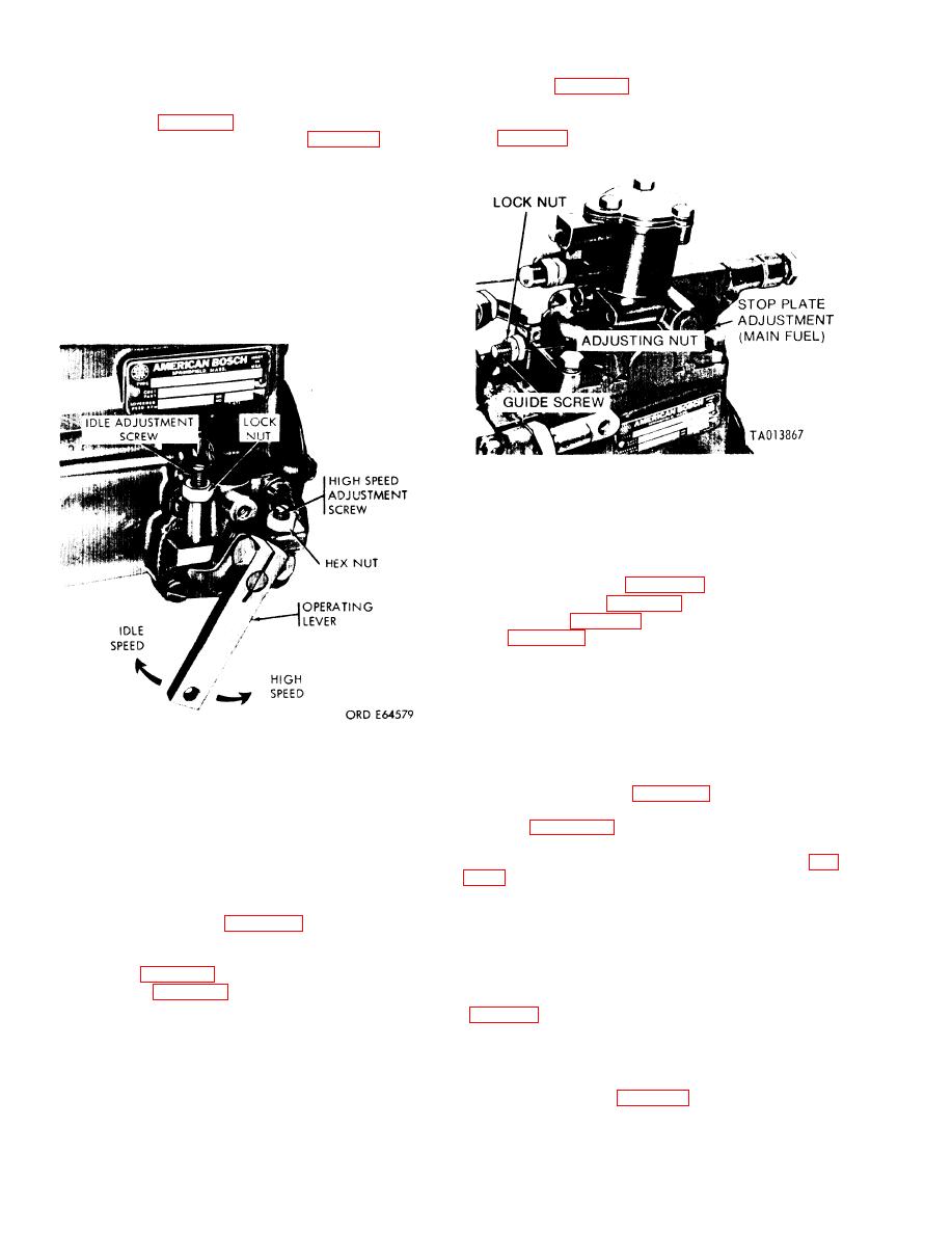
Figure 3-173. Idle and High speed adjustment. |
|
||
| ||||||||||
|
|
 TM 9-2910-226-34
linkage (para 3-25). Replace defective parts,
supply filters. Then if pressure is still low, replace
and repeat the tests to obtain specified fuel
the over-flow valve. Fuel flow should be in ac-
flow. Check governor spring and spacers
cordance with Table 3-4 or 3-5, depending on pump
used. If reading in the burette (F, fig. 3-162) is not
within specifications, push in the fuel dumping lever
(E) to clear the burettes, and repeat test. If reading
is not within specifications, push in fuel dumping
lever to clear burettes. Fuel flow adjustment is made
by adjusting high speed adjustment screw (fig. 3-
173). Loosen the hex nut and turn the screw clock-
wise to decrease, or counterclockwise to increase the
fuel delivery. Make adjustments and repeat test
until specified fuel flow is attained. Tighten hex nut
to lock setting of the high-speed adjustment screw
F'igure 3-174. Adjusting stop plate guide screw and stop plate
for desired fuel delivery (code C, D, and E pumps).
(4) Increase pump speed to 2940 rpm and check
fuel flow. Flow should be 5 cc or less. If reading of 5
cc or less is not obtained, it will be necessary to stop
the test and check the high speed (inner) governor
spring spacer(s). See Table 3-11 for proper spacer
dimensions (refer to para 3-43). Check for use of the
correct spring (fig. 3-143). Check control unit for pin
wear (para 3-44).
NOTE
Adding spacers to the governor spring will
increase fuel delivery, and decreasing
spacers will decrease fuel delivery. Repeat
2940 rpm fuel flow check, and add or remove
spacers to obtain a fuel flow of 5 cc
Figure 3-173. Idle and High speed adjustment.
maximum.
(5) Adjust speed to 1400 rpm and check fuel
Table 3-10. Fuel Supply Pump Pressure (To Hydraulic Head)
pressure on gage (A, fig. 3-162) at compensator
inlet. Fuel pressure should be 40-55 psi. Check fuel
Speed [rpm]
Pressure [psi]
flow per Tables 3-5 or 3-4 respectively. (This is a
2600-3100
60-80
reference point only,) No adjustment is required on C
1200
40-55
and D pumps. Adjust setscrew (droop screw) (J, fig.
700
30-40
150
7 (min. )
decrease fuel delivery, and counterclockwise to
(3) Adjust speed to 2600 rpm and check fuel
increase fuel delivery. (Code C and D pumps do not
pressure on gage (A, fig. 3-162) at compensator
have a droop screw.)
inlet. Fuel pressure should be 60-80 psi. Adjust stop
(6) If fuel flow cannot be adjusted to these
plate guide screw (fig. 3-174) on code C, D, and E
limits, check engagement of compensator stop plate
pumps, or (fig. 3-172) on code G pumps, to obtain
and linkage on code C, D, and E pumps and angular
fuel flow per Table 3-4 or 3-5.
position of smoke limit torque cam on all pumps
NOTE
Turn stop plate adjusting nut clockwise to
a greater angle will increase fuel flow and decreasing
decrease fuel and counterclockwise to in-
the cam angle will decrease the flow. Recheck fuel
crease fuel, as viewed at the governor end of
flow.
the pump. If fuel flow limit can not be ob-
(7) Reduce speed to 700 rpm and check fuel
tained by adjusting the stop plate, it will be
pressure on gage (A, fig. 3-162) at compensator inlet
necessary to inspect the fuel control rod
(code C, D, and E pumps) or head inlet (code G
3-106
|
|
Privacy Statement - Press Release - Copyright Information. - Contact Us |
