 |
|||
|
|
|||
|
Page Title:
Table 3-9. Temperature of Specific Gravity Conversion |
|
||
| ||||||||||
|
|
 TM 9-2910-226-34
fuel temperature to 150 F. as indicated on the fuel
(1) All new fuel injection pump assemblies
temperature gage (B). Fuel pressure to hydraulic
from stock, as well as service and repaired pumps
head (compensator inlet) should be within. limits
must be calibrated on a test stand, using calibration
shown in table 3-10 during testing of pumps.
limits tables 3-4 through 3-7, before installation on
an engine.
NOTE
(2) The fuel injection pump must be completely
Run test stand long enough for the fuel to
assembled for this test. Fuel density compensator
heat to 140 F. Adjust heater control as
assemblies may be new, functionally checked in
necessary to obtain this temperature.
accordance with paragraph 3-24.
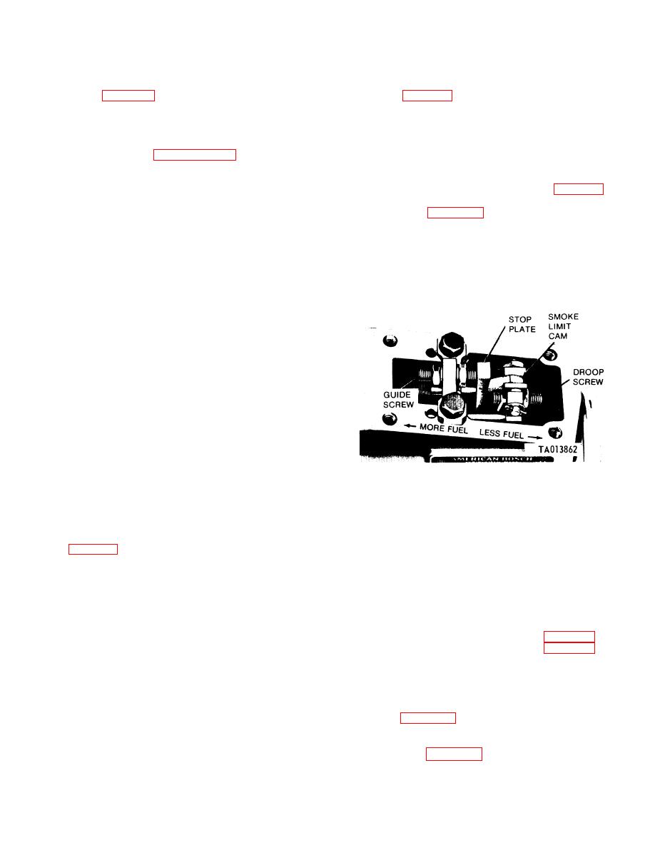
(11) Remove operating lever dust cover.
(3) Push the test stand 24-volt button (P). The
Remove socket head pipe plug from rear of governor
power ON light (Z) should glow. Turn the auxiliary
housing on code A, B, E, and F pumps (fig. 3-163).
motor switch (AA) to the ON position.
(On code G pumps remove governor cover.) Back out
(4) Turn on the lube heat switch (T) to bring oil
droop screw (fig. 3-172) sufficiently to insure
to 150 on the lube oil temperature gage (C).
clearance between droop screw and stop plate, with
(5) Adjust the lube oil regulator (JJ) to obtain
operating lever in full-throttle position. The droop
an oil pressure of 35-45 psi on lube oil pressure gage
screw must not be in contact with the stop plate
when setting full throttle fuel flow. Install governor
pump internally.
cover on code G pumps.
Table 3-9. Temperature of Specific Gravity Conversion
Temperature
Specific
in degrees F.
gravity
60
0.810-0.830
65
0.808-0.828
70
0.806-0.826
75
0.804-0.824
80
0.802-0.822
85
0.800-0.820
90
0.798-0.818
95
0.797-0.816
100
0.795-0.815
105
0.793-0.813
110
0.791-0.811
115
0.789-0.809
120
0.787-0.807
125
0.785-0.805
130
0.783-0.803
NOTE
Hydrometer, 6630.350-9431 is available.
Figure 3-172. Adjusting droop screw and stop plate guide screw
(6) Turn on the fuel heat switch (R) to bring fuel
for desired fuel delivery (code G pumps).
temperature within range listed on calibration
tables. Check temperature on gage (B).
NOTE
(7) Open suction valve of fuel supply hose (A,
Sub paragraph (11) above does not apply to
code C and D pumps as a droop screw is not
3-5 psi on gage (GG) at supply pump inlet.
used on these pumps.
(8) Set 500-1000-OFF count switch (V) at 1000,
(12) Check fuel return pressure on gage at
the FORWARD-OFF-REVERSE switch (CC) at the
pump overflow valve outlet. Pressure should not be
REVERSE position, and the test stand speed
greater than 5 psi. If pressure exceeds 5 psi, replace
shifting crank (S) at "High Range" position. Slowly
pump overflow valve.
increase fuel pressure by turning regulator (HH)
c. Calibration of Code C, D, E, and G Pumps.
until the overflow valve opens. This can be observed
Calibrate code C, D, and G pumps using Table 3-5 as
since the fuel pressure gage (A) will show a sudden
reference. Calibrate code E pumps using Table 3-4 as
drop in pressure. Record the pressure. The valve
reference.
should open at 33-38 psi. If not, replace the overflow
(1) Use two-hole injector nozzle and holder
valve and repeat the test. Reset fuel pressure to 5
assemblies.
psi.
(2) Adjust speed to 2850 rpm with operating
(9) Push in drive motor start button (EE) and
lever in full-fuel position and check fuel pressure on
adjust speed to 600 rpm. Maintain this speed for five
gage (A, fig. 3-162) at compensator inlet. Fuel
minutes to allow for warm-up.
pressure on fuel pressure gage (A) should be 60-80
(10) Turn lube oil regulator (JJ) to bring oil
psi. If fuel pressure is below 60 psi, inspect fuel
temperature to 150 degrees F. on the lube oil tem-
supply pump (para 3-20) and the test stand fuel
perature gage (C). Turn fuel heat switch (R) to bring
3-105
|
|
Privacy Statement - Press Release - Copyright Information. - Contact Us |
