 |
|||
|
|
|||
|
Page Title:
Hydraulic Head Port Closing Test. |
|
||
| ||||||||||
|
|
 TM 9-2910-226-34
f. Connect outlet of the nozzle tester to the im-
provised adapter using a high pressure hose.
g. Install locally fabricated U tube in the No. 1
hydraulic head outlet. Position a plastic container
under the open end of the U tube to collect test oil
(which will be returned to the tester reservoir) (fig. 3-
164).
h. Remove timing device cover and timing
window cover, or fuel shutoff housing.
3-53. Hydraulic Head Port Closing Test. a. Secure
the throttle lever in the full fuel position with a
spring or other suitable device (fig. 3-163).
and delivery valve spring (B). Reinstall delivery
valve screw.
NOTE
Delivery valve is matched to the hydraulic
head. Do not replace or interchange valve.
c. Apply 3-10 psi test oil pressure to the hydraulic
head with the nozzle tester. Loosen the in, pipe
plug in the hydraulic head overflow valve opening to
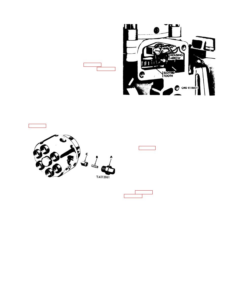
Figure 3-167. Alining slotted tooth with arrow on housing.
bleed air from the head. Tighten plug.
NOTE
d. Rotate the test stand drive coupling clockwise
The scribed mark on the advance unit hub
(as viewed from the drive end) with the test stand
should not be alined with its pointer,
spanner wrench until the slotted, red painted tooth is
e. Slowly continue to rotate the drive hub in a
visible in the timing window on the pump housing
clockwise direction (as viewed from the drive end)
until the test oil begins to form droplets at the end of
the U-tube. Slowly continue to rotate the drive hub
until the test oil flows freely and then diminishes and
stops. This is port closing. The scribed mark on the
advance unit hub should now be alined with the
pointer (fig. 3-168) and the slotted, red painted tooth
in the timing window should be one tooth to the right
of the mark on the pump housing. If the above
specification is not met, the hydraulic head, tappet
assembly and/or camshaft must be replaced. If the
plunger button is damaged, hydraulic head must be
replaced.
f. Install the timing device cover using a new
gasket, and tighten the retaining bolts and lock-
washers fingertight. Install timing window cover or
A Delivery valve screw
fuel shutoff housing. Remove U-tube from hydraulic
B Delivery valve spring
head (fig. 3-164). Remove delivery valve screw (A,
C Fuel delivery valve
Figure 3-166. Installing fuel delivery valve and screw.
3-97
|
|
Privacy Statement - Press Release - Copyright Information. - Contact Us |
