 |
|||
|
|
|||
|
Page Title:
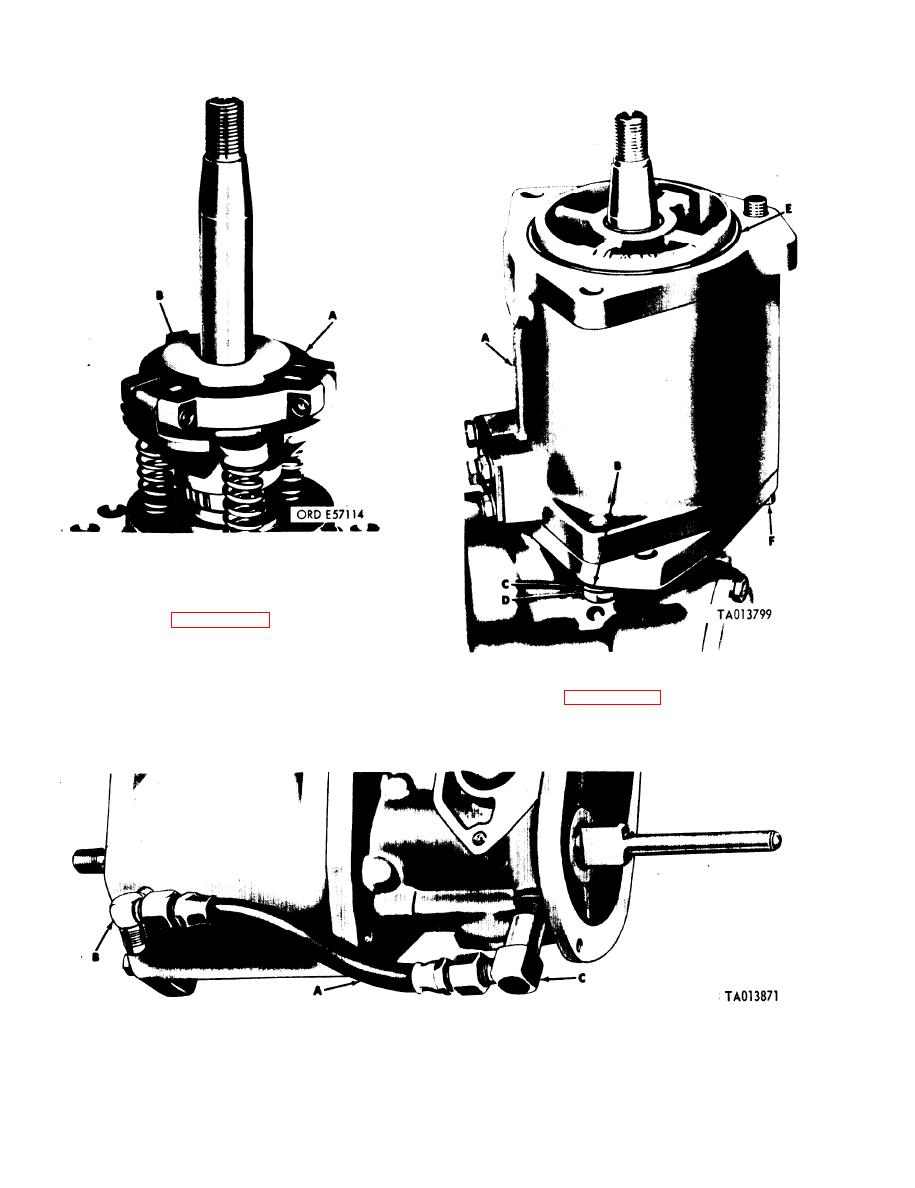
Figure 3-134. Installing spider assembly, spacer, and thrust plate. |
|
||
| ||||||||||
|
|
 TM 9-2910-226-34
Figure 3-134. Installing spider assembly, spacer, and thrust plate.
Install the timing device
b.
Installation.
assembly as follows:
(1) Refer to figure 3-135. Install bolt (F) in
pump and timing device housing before assembly of
timing device housing to pump housing. Install
timing device housing (A), after checking to see if
Figure 3-135. Installing timing device housing.
pump housing packing is in position, and secure with
(2) Refer to figure 3-136. Install pipe-to-tube
two flat washers (B), lockwashers (C), and machine
elbow (C), pipe-to-tube tee (B), and oil distribution
screws (D). Torque tighten machine screws to 17-20
hose assembly (A).
foot-pounds. Install housing packing (E).
Figure 3-136. Installing oil distribution hose assembly and fittings.
3-80
|
|
Privacy Statement - Press Release - Copyright Information. - Contact Us |
