 |
|||
|
|
|||
|
Page Title:
Repair of Fuel Injection Pump Housing |
|
||
| ||||||||||
|
|
 TM 9-2910-226-34
(2) Refer to figure 3-105 and install bearing
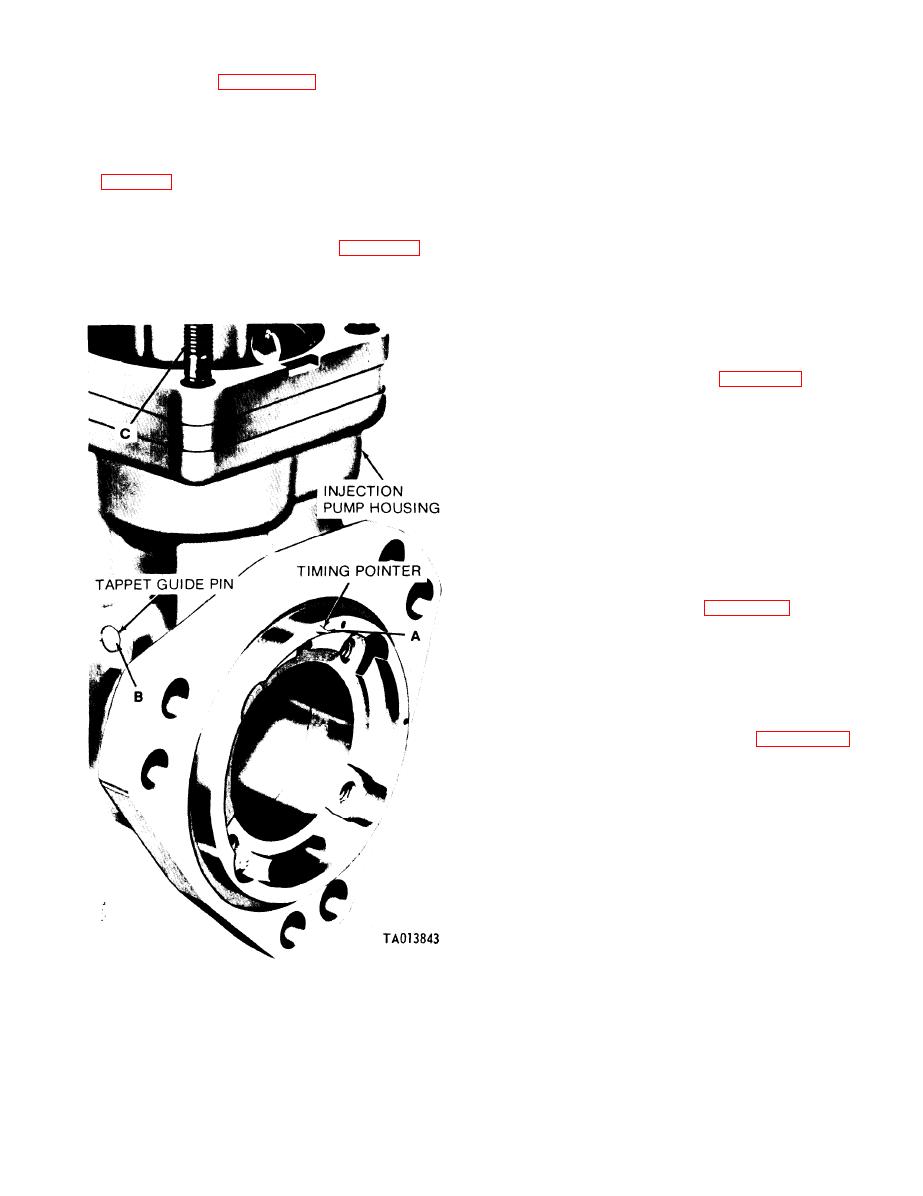
b. Examine the timing pointer (A), tappet guide
retaining locknut and related parts on camshaft.
pin (B), and studs (C) for wear and damage. If any
Torque tighten nut to 25-40 foot-pounds. Secure nut
part is defective replace the pump assembly.
by bending tab of lockwasher into notch of locknut.
c. Inspect the camshaft bushing type bearing for
score marks and wear patterns. Replace housing if
Fuel
Injection
Pump
3-32. Repair of
bearing is damaged or worn. Retain housing for
Housing. a. Inspect the injection pump housing
possible repair if `bearing is defective.
3-33. Repair of Miscellaneous Components. a.
pump when housing is cracked. Minor nicks or burs
may be removed with a fine mill file or crocus cloth.
General. The following paragraphs cover inspection
Check the injection pump housing against the limits
and repair of miscellaneous components. The
components covered in these paragraphs are external
specified in the repair standards (para 3-60) and
components and are not necessarily part of the
replace the pump when housing does not meet these
assemblies repaired in the preceding paragraphs.
requirements.
preceding paragraphs.
NOTE
Paragraph b applies only to code F and G
pumps.
oil filter (C). Inspect oil filter screw (A) for stripped
threads or other damage. If filter (C) or screw (A) are
damaged replace the hydraulic head assembly and
plug housing opening using kit 5704374 to plug oil
passage in pump housing.
c. Repair of Oil Hose Assembly. Refer to figure 3-
35. Inspect oil hose assembly (X) for damage,
damaged fittings, stripped threads, and
deterioration to hose structure. Replace hose
assembly if damaged. Check elbow (Y) and tee (W)
for cracks and damaged threads. Replace if
damaged.
d. Repair of Stop Plate and Bridge Assembly.
(Code G pumps only.) Refer to figure 3-12. Inspect
stop plate (F) for wear or damaged threads. Install
nut (E) and lockwasher (D) on screw of stop plate
(F). Position bridge (C) on stop plate screw with
approximately seven exposed threads between nut
(E) and stop plate. Secure with lockwasher (B) and
nut (A).
e. Repair of Plastic Lines and Fittings. There is
no repair of plastic lines and fittings, figures 3-29
through 3-33. Inspect for damage and replace lines
and fittings as required.
Figure 3-108. Location of timing pointer and tappet guide pin.
3-67
|
|
Privacy Statement - Press Release - Copyright Information. - Contact Us |
