 |
|||
|
|
|||
|
Page Title:
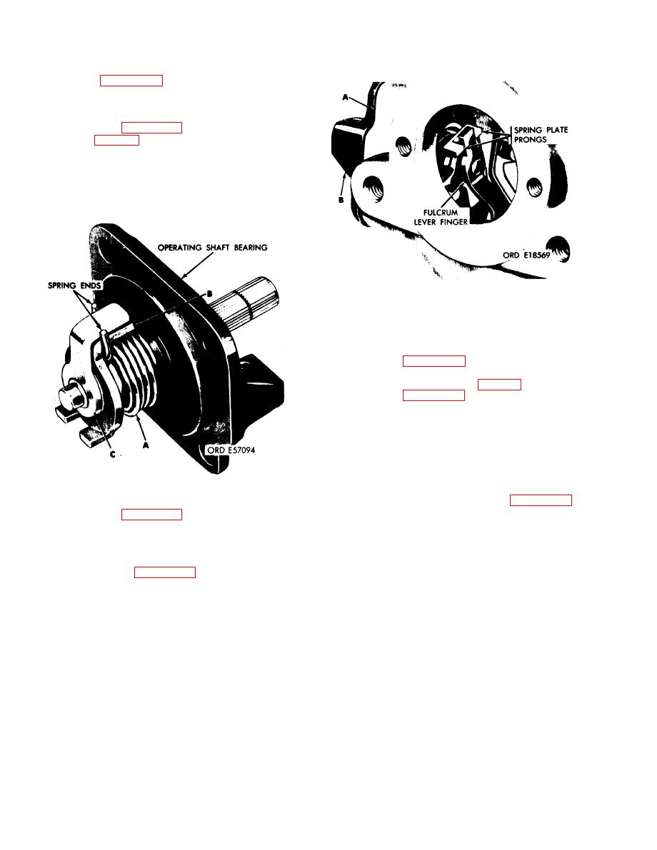
Figure 3-76. Assembling operating shaft bearing and associated parts. |
|
||
| ||||||||||
|
|
 TM 9-2910-226-34
NOTE
Refer to figure 3-75 for selection of proper
operating shaft bearing and operating shaft
spring plate for each pump. All operating
shafts should have a retaining ring groove.
(5) Refer to figure 3-76. Install operating shaft
packing (D, fig. 3-62) on operating shaft. Install the
operating shaft spring (A) on the shaft spring plate
(B) with the spring ends gripping the tang on the
shaft spring plate. Install the shaft spring plate and
operating shaft spring on the operating shaft
bearing. Install operating shaft (C) so its arm is
between spring ends.
Figure 3-77. Installing operating shaft bearing and associated
parts in governor housing.
NOTE
Sub-paragraphs (7) through (12) below apply
only to code A pumps.
(7) Refer to figure 3-74. Install fulcrum lever
assembly in governor housing. Fulcrum lever pivot
pin must have a dimension (X) (fig. 3-67) of 0.204.
(8) Refer to figure 3-66 and install two inside
washers (B) on pins (E). Assemble the torque link
(C) to the operating shaft (D). Secure with two
outside washers (B) and lock pins (A). Torque link
should operate freely on pins. Assemble spring
washer (K) inside flat washer (H) stop (J) in position
shown out side flat washer (H) on torque link and
retain with cotter pin (G). Install new packing (F) on
Figure 3-76. Assembling operating shaft bearing and
operating shaft. Install operating shaft and torque
associated parts.
link assembly in governor housing per figure 3-65.
NOTE
(6) Refer to figure 3-77. Install operating shaft
The torque link stop is furnished with the
bearing gasket (A) and operating shaft bearing and
density compensator. The stop furnished
associated parts (B) on governor housing. Spring
with the new compensator should be in-
plate prongs must engage fulcrum lever finger.
stalled with the compensator.
Groove in end of operating shaft must be vertical
when installed, see figure 3-61.
3-52
|
|
Privacy Statement - Press Release - Copyright Information. - Contact Us |
